Rating:
Information holder & nozzle se Denso
Product
Nozzle & Nozzle Holder
Vehicle engine
INDUSTRIAL 4M40
Engine
4M40
Serial start-end
9512-
Info
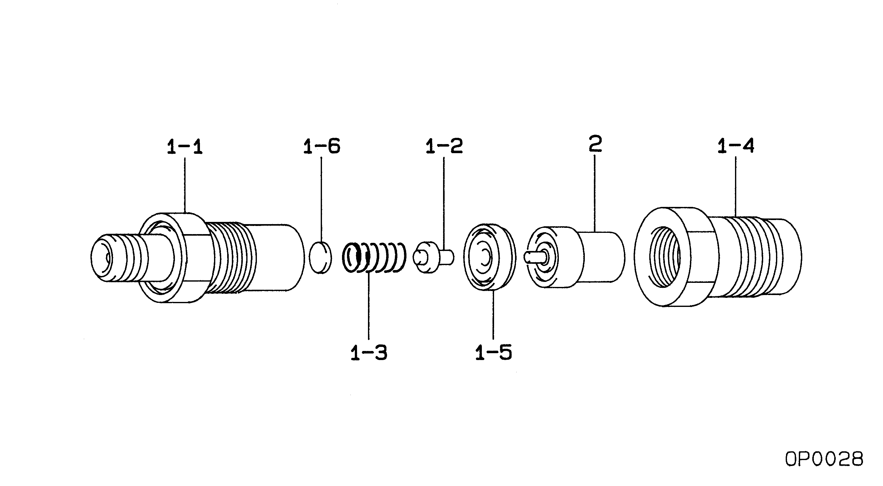
Injector Nozzle
Components :
Scheme #.#:
№
Qty
Part num
Name
Remarks
Manufacture num
000
[01]
09350-06430
HOLDER & NOZZLE SE
Include in ##:
09350-06430
as HOLDER & NOZZLE SE
Nozzle Specification:
Parts number
0935006430 MITSUBISHI
Nozzle
0934005490
First opm
11.27-12.25
First op
115-125
Second om
-
Second op
-
Torquen
44.1-49.0
Torque
4.5-5.0
Prelift
-
Max lift
Engine
INDUSTRIAL 4M40
Information
Cross reference number
Part num
Firm num
Firm
Name
09350-06430
HOLDER & NOZZLE SE
Information:
Introduction
The problem that is identified below has a known solution. Use the solution that is identified below.Problem
The procedure for the Disassembly and Assembly needs to be updated to include the information below.Solution
Do not operate or work on this product unless you have read and understood the instruction and warnings in the relevant Operation and Maintenance Manuals and relevant service literature. Failure to follow the instructions or heed the warnings could result in injury or death. Proper care is your responsibility.
Inspect the quill tubes and fuel injectors for cuts or marks at the mating surfaces.
Replace any quill tubes since the quill tubes are a one time use component. Replace the copper washer when replacing the fuel injector.
Follow the steps below for installing the quill tunes and fuel injectors.
Seat the injector by installing and torquing the injector hold down clamp bolt to 30 3 N m (22 2 lb ft).
Install the quill tube and tighten the quill nut between 15 N m (11 lb ft) to 20 N m (15 lb ft).
Apply a final torque of 30 3 N m (22 2 lb ft) to the injector hold down clamp bolt.
Apply a final torque between 50 N m (37 lb ft) to 55 N m (41 lb ft).