Rating:
Information holder & nozzle se Denso
Product
Nozzle & Nozzle Holder
Vehicle engine
CANTER 4D36
Engine
4D36
Serial start-end
9311-
Info
Injector Nozzle
Components :
Scheme #.#:
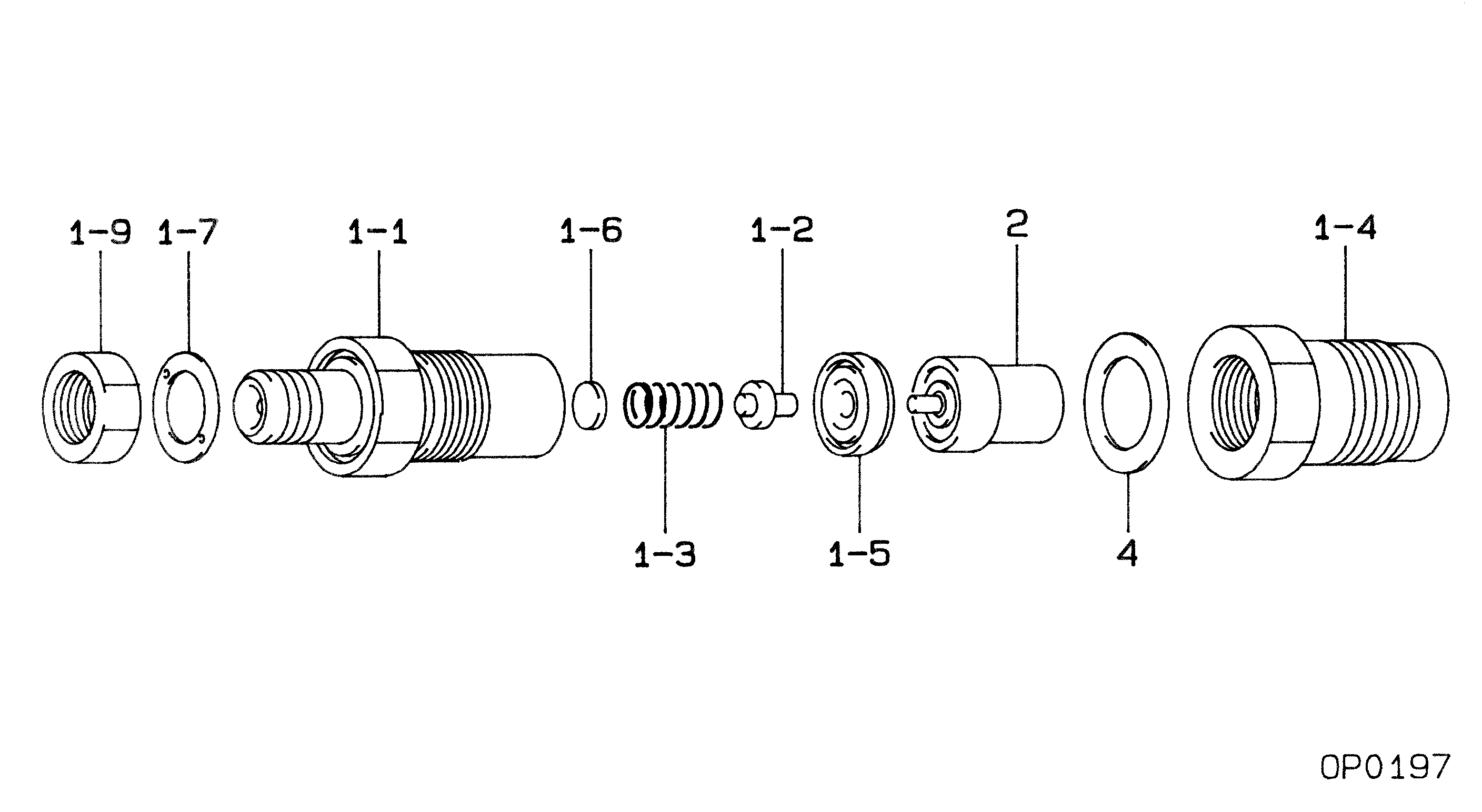
№
Qty
Part num
Name
Remarks
Manufacture num
000
[01]
09350-05940
HOLDER & NOZZLE SE
ME016995
MITSUBISHI
Include in ##:
09350-05940
as HOLDER & NOZZLE SE
Nozzle Specification:
Parts number
0935005940 MITSUBISHI
Nozzle
0934002951
First opm
11.76-12.74
First op
120-130
Second om
-
Second op
-
Torquen
58.8-78.4
Torque
6.0-8.0
Prelift
-
Max lift
Engine
CANTER 4D36
Information
Include as Nozzle:
Cross reference number
Part num
Firm num
Firm
Name
09350-05940
ME016995
HOLDER & NOZZLE SE
0935005940
ME016995
MITSUBISHI
HOLDER & NOZZLE SE
Information:
Personal injury or death can result from machine articulation or movement. Machine frames can move and a person can be crushed. Connect the steering frame lock between the front and rear frames before working on the machine.Before operating the machine, place the steering frame lock in the stored position.Failure to place the steering frame lock into the stored position before operating can result in loss of steering.
Reference: Disassembly and Assembly, M0084637, "R1700 Load Haul Dump Machine Systems"Reference: Disassembly and Assembly, M0100022, "R2900 Load Haul Dump Machine Systems"Required Parts
Table 1
Required Parts
Qty Part Number Description
1 389-9442 Insulation
1 434-1304 Insulation
1 434-1305 Insulation
7 290-1993 Cable Strap Machine Preparation
Note: Cleanliness is an important factor. Before the removal procedure, clean the exterior of the component thoroughly. Cleaning the exterior will help to prevent dirt from entering the internal mechanism.
Move the machine to a hard level surface away from operating machines and away from personnel.
Engage the parking brake. Place wheel blocks in front of the wheels and behind the wheels.
Stop the engine.
Install the steering frame lock. Refer to Disassembly and Assembly, "Steering Frame Lock - Install".
Turn the key start switch and the battery disconnect switch to the OFF position. If there is no battery disconnect switch, remove the negative battery cable at the battery.
Release system pressure. Refer to Operation and Maintenance Manual, "System Pressure - Release".Procedure
Illustration 1 g06525155
Typical example
(1) Cover As
(2) Cover As
Remove cover assembly (1) and cover assembly (2).
Illustration 2 g06525163
Typical example
(3) Hose As
Locate DEF supply hose assembly (3).
Illustration 3 g06526653
DEF supply hose on the R1700 machine
(4) 290-1993 Cable Strap
(5) 389-9442 Insulation
(6) 434-1305 Insulation
(7) 434-1304 Insulation
Illustration 4 g06526655
DEF supply hose on the R2900 machine
(4) 290-1993 Cable Strap
(5) 389-9442 Insulation
(6) 434-1305 Insulation
(7) 434-1304 Insulation
Install Item (5) through Item (7), securing with 290-1993 Cable Straps as required.Note: On the R1700 machine, 434-1305 Insulation (6) is installed over the top of 389-9442 Insulation (5).Note: On the R2900 machine, 434-1305 Insulation (6) slightly overlaps 389-9442 Insulation (5).
Install cover assembly (1) and cover assembly (2). Refer to Illustration 1.