Rating:
Information holder & nozzle se Denso
Product
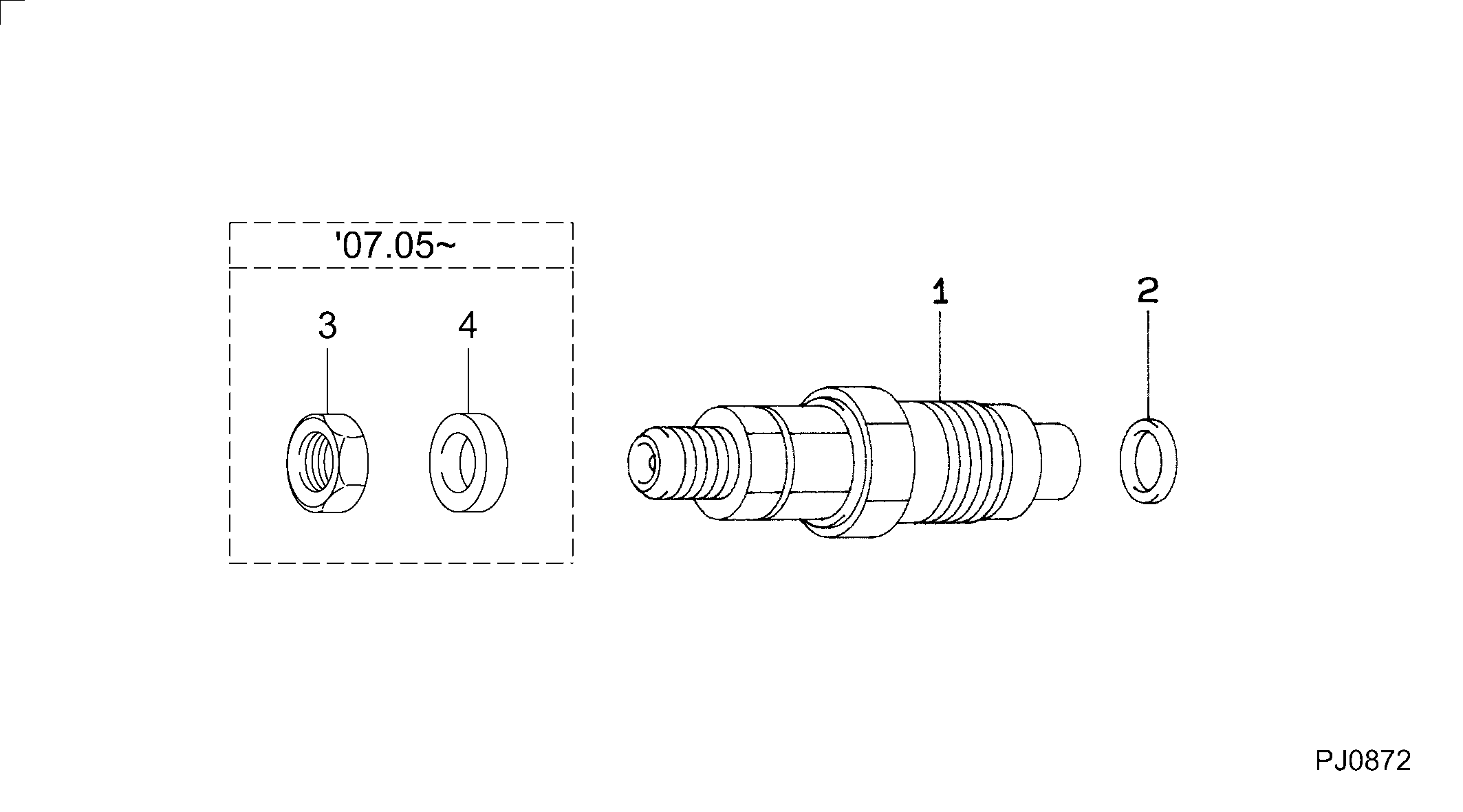
Nozzle & Nozzle Holder
Vehicle engine
COASTER 1HZ-T
Engine
1HZ-T
Serial start-end
9211-
Info
093500-5500 consists of 093500-5770 and a gasket as a spare parts kit.
Injector Nozzle
Compare Prices: .
As an associate, we earn commssions on qualifying purchases through the links below

23600-19035 Engine Fuel injector Nozzle Compatible for Land Cruiser 1HZ 1HZT HZJ76 4.2D 1993-2012 093500-5770 093100-5500
PKZLINJQ 23600-19035 Engine Fuel injector Nozzle Compatible for Land Cruiser 1HZ 1HZT HZJ76 4.2D 1993-2012 093500-5770 093100-5500 || The fuel injector balances fuel delivery, which can improve engine performance, effectively take car shaking off and enhance your driving experience. || The design of automobile fuel injector can accurately control the fuel injection quantity, thus optimizing fuel economy and helping you save fuel costs. || By improving combustion efficiency, our fuel injectors help reduce fuel consumption and provide a more economical driving experience for your vehicle. || Our automobile fuel injectors are manufactured with precision and strictly controlled by quality, providing excellent durability and ensuring long-term stable use.
PKZLINJQ 23600-19035 Engine Fuel injector Nozzle Compatible for Land Cruiser 1HZ 1HZT HZJ76 4.2D 1993-2012 093500-5770 093100-5500 || The fuel injector balances fuel delivery, which can improve engine performance, effectively take car shaking off and enhance your driving experience. || The design of automobile fuel injector can accurately control the fuel injection quantity, thus optimizing fuel economy and helping you save fuel costs. || By improving combustion efficiency, our fuel injectors help reduce fuel consumption and provide a more economical driving experience for your vehicle. || Our automobile fuel injectors are manufactured with precision and strictly controlled by quality, providing excellent durability and ensuring long-term stable use.
You can buy:

Components :
Scheme #.#:
№
Qty
Part num
Name
Remarks
Manufacture num
000
[01]
09350-05770
HOLDER & NOZZLE SE
Include in ##:
09350-05770
as HOLDER & NOZZLE SE
Nozzle Specification:
Parts number
0935005770 TOYOTA
Nozzle
0934005200
First opm
14.21-15.19
First op
145-155
Second om
-
Second op
-
Torquen
34.3-39.2
Torque
3.5-4.0
Prelift
-
Max lift
Engine
COASTER 1HZ-T
Information
093500-5770 consists of 093500-5500 and a gasket as a spare parts kit.
Include as Nozzle:
Cross reference number
Part num
Firm num
Firm
Name
09350-05770
HOLDER & NOZZLE SE
Information:
Introduction
If the engine turns over but the engine does not start, refer to Operation and Maintenance Manual, "Fuel System - Prime" and Troubleshooting, "Engine Cranks but Will Not Start".If the engine will not start, new service parts are available.The new service parts are the following components.
257-2382 Plug
257-2381 Pin
258-8149 Spring Removal Procedure
Contact with high pressure fuel may cause fluid penetration and burn hazards. High pressure fuel spray may cause a fire hazard. Failure to follow these inspection, maintenance and service instructions may cause personal injury or death.
Ensure that all adjustments and repairs that are carried out to the fuel system are performed by authorised personnel that have the correct training.Before begining ANY work on the fuel system, refer to Operation and Maintenance Manual, "General Hazard Information and High Pressure Fuel Lines" for safety information.Refer to Systems Operation, Testing and Adjusting Manual, "Cleanliness of Fuel System Components" for detailed information on the standards of cleanliness that must be observed during ALL work on the fuel system.
Care must be taken to ensure that fluids are contained during performance of inspection, maintenance, testing, adjusting and repair of the product. Be prepared to collect the fluid with suitable containers before opening any compartment or disassembling any component containing fluids.Dispose of all fluids according to local regulations and mandates.
Note: Put identification marks on all hoses and all plastic tube assemblies for installation purposes. Plug all plastic tube assemblies. This helps to prevent fluid loss and this helps to keep contaminants from entering the system.
Turn the fuel supply to the OFF position.
Turn the battery disconnect switch to the OFF position.
Illustration 1 g02028780
Typical example
Illustration 2 g02030553
Typical example
Remove one outlet check plug (2) from fuel injection pump (1). Remove the plug, the spring (5) and the outlet check valve (4) .
Clean the components with alcohol or contact cleaner. Inspect the components for wear or damage. If there is damage to the radius surface of the outlet check valve, replace with a new outlet check valve.
Flush out the head of the fuel injection pump (1) with clean alcohol or contact cleaner. Inspect the head of the fuel injection pump (1) for damage or debris on the seat area (3) .
Use a cotton swab with alcohol or contact cleaner applied, swab threads in counterclockwise direction. This will remove debris from the threads.Note: Caution is required to prevent pushing debris into the internal passages. Do not use a clockwise direction to clean debris from threads as debris could be pushed into the fuel injection pump.Installation Procedure