Rating:
Information holder & nozzle se Denso
Product
Nozzle & Nozzle Holder
Vehicle engine
INDUSTRIAL Z500
Engine
Z500
Serial start-end
8708-
Info
Injector Nozzle
Components :
Scheme #.#:
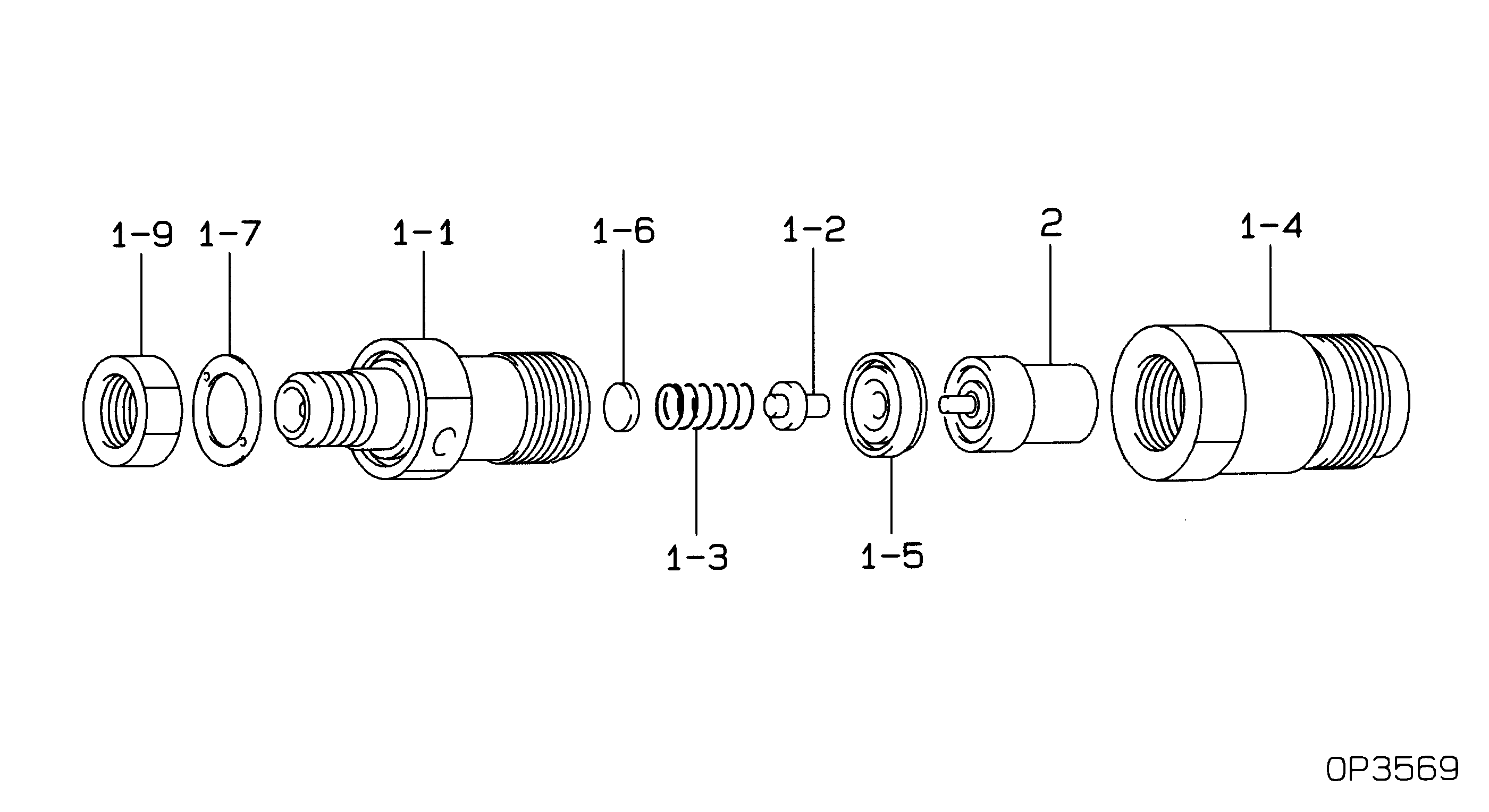
№
Qty
Part num
Name
Remarks
Manufacture num
000
[01]
09350-03920
HOLDER & NOZZLE SE
Include in ##:
09350-03920
as HOLDER & NOZZLE SE
Nozzle Specification:
Parts number
0935003920 KUBOTA
Nozzle
0934000100
First opm
13.72-14.70
First op
140-150
Second om
Second op
Torquen
39.2-49.0
Torque
4.0-5.0
Prelift
Max lift
Engine
INDUSTRIAL Z500
Information
Cross reference number
Part num
Firm num
Firm
Name
09350-03920
HOLDER & NOZZLE SE
Information:
1. Disconnect hose assemblies (4) and (5) from elbow (6).2. Loosen the clamps that hold hose (1) in place. and move hose (1) away from elbow (6).3. Remove the bolt, lock and elbow (6) from the turbocharger.4. Loosen the clamps that hold elbow (7) in place, and move the elbow away from the turbocharger.5. Remove tube assemblies (8) and (9).6. Remove the clamp that holds pipe assembly (2) in position, and move the pipe assembly away from the turbocharger.7. Fasten a hoist to turbocharger (3). Remove the nuts that hold the turbocharger to the exhaust manifold, and remove the turbocharger. The weight of the turbocharger is 23 kg (51 lb.). The following steps are for installation of the turbocharger.8. Install the gasket between the turbocharger (3) and the exhaust manifold. Put 5P3931 Anti-Seize Compound on the threads of the bolts, and install the bolts and nuts that hold the turbocharger to the exhaust manifold. Tighten the bolts to a torque of 55 5 N m (41 4 lb.ft.).9. Make sure the gaskets are in position on tube assemblies (8) and (9), and install the tube assemblies.10. Put pipe assembly (2) in position on the turbocharger, and install the clamp that holds it.11. Put elbow (7) in position on the turbocharger, and install the clamps that hold it in place.12. Put elbow (6) in position in the turbocharger and hose (1). Tighten the clamps that hold the hose to the elbow.13. Install the lock and bolt to hold elbow (6) in position in the turbocharger.14. Connect hose assemblies (4) and (5) to elbow (6).Disassemble Turbocharger
1. Install the turbocharger on tool (A) as shown.2. Put alignment marks on three housings of the turbocharger for correct alignment during assembly. Loosen clamp (2), and remove the clamp and housing (1) from housing assembly (3). 3. Loosen clamp (4), and remove housing assembly (3) from housing (5). 4. Put the cartridge group in position in tool (B) as shown.
When the nut is loosened, do not put a side force on the shaft. This can result in a bent shaft.
5. Use a 5S9566 Sliding T-Wrench and a universal socket (6) to remove the nut that holds the compressor wheel to the wheel assembly.6. Remove compressor wheel (7) and the shims from wheel assembly (8).7. Remove housing assembly (3) from wheel assembly (8). 8. Remove ring (9) and backplate (10) from wheel assembly (8). 9. Use tool (C), and remove snap ring (11) from housing assembly (3). 10. Remove insert (12) and sleeve (13) from housing assembly (3). 11. Remove ring (14) from sleeve (13). 12. Remove two screws (15) and deflector (16) from housing assembly (3). 13. Remove ring (18) and bearing assembly (17) from the housing assembly. 14. Remove sleeve (19) and ring (20) from the housing assembly. 15. Remove O-ring seal (23) from the housing assembly.16. Use tool (D), and remove snap ring (22) from the housing assembly.17. Remove bearing (21). Remove the snap ring behind the bearing with tool