Rating:
Information holder & nozzle se Denso
Product
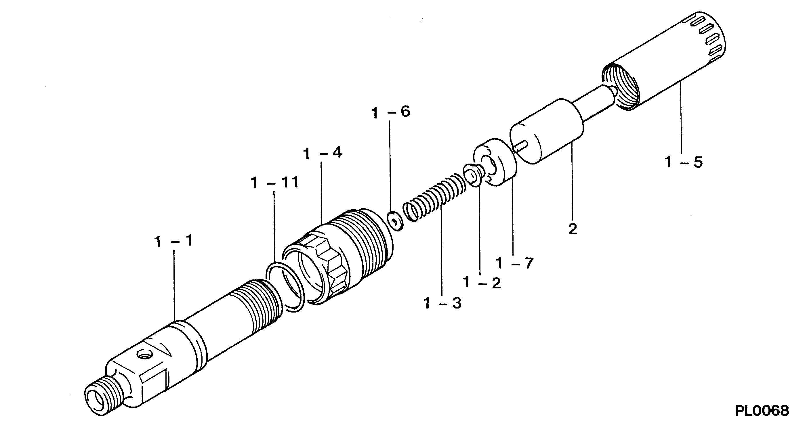
Nozzle & Nozzle Holder
Vehicle engine
INDUSTRIAL 6466A
Engine
6466A
Serial start-end
8601-
Info
Injector Nozzle
Components :
Scheme #.#:
№
Qty
Part num
Name
Remarks
Manufacture num
Nozzle Specification:
Parts number
0935003420 JOHN DEERE
Nozzle
0934005341
First opm
25.97-26.95
First op
265-275
Second om
-
Second op
-
Torquen
-
Torque
-
Prelift
-
Max lift
Engine
INDUSTRIAL 6466A
Information
Include as Nozzle:
Cross reference number
Part num
Firm num
Firm
Name
09350-03420
HOLDER & NOZZLE SE
Information:
Introduction
This Special Instruction provides the rework procedure for the installation of the 254-4334 Check Valve Kit on the 228-5896 Unit Injector Hydraulic Pump Gp and the 228-5898 Unit Injector Hydraulic Pump Gp . The parts kit includes a temporary service bolt that is used during the removal of the fuel transfer pump in order to prevent the body of the unit injector hydraulic pump from separating. Once the fuel transfer pump has been reinstalled onto the HEUI pump, the service bolt is then removed.
The correct procedures and tooling specifications must always be used. Failure to follow any of the procedures may result in damage, malfunction, or possible engine failure.
Keep all parts clean from contaminants.Contaminants may cause rapid wear and shortened component life.
Care must be taken to ensure that fluids are contained during performance of inspection, maintenance, testing, adjusting and repair of the product. Be prepared to collect the fluid with suitable containers before opening any compartment or disassembling any component containing fluids.Refer to Special Publication, NENG2500, "Caterpillar Tools and Shop Products Guide" for tools and supplies suitable to collect and contain fluids on Caterpillar products.Dispose of all fluids according to local regulations and mandates.
Table 1
Required Tools
Tool Part Number Description
A 194-3533 T20 Torx bit (1)
B 193-9199 T27 Torx bit (1)
C 194-3536 T40 Torx bit (1)
D 6 mm Hex Key Wrench
Torque Wrench (in lb)
Torque Wrench (ft lb)
1U-6396 O-Ring Assembly Compound
( 1 ) Or Equivalent
Table 2
254-4334 Check Valve Kit
Callout Part Number Description Qty
5 227-5904 O-Ring Seal 1
9 256-0302 Service Bolt 1
10 239-2402 Seal 2
11 179-8128 Seal 1
12 254-4302 Check Valve Assembly 7 Removal of the HEUI Pump
Prior to removing the HEUI pump, wash the engine in order to remove all of the dirt from the area that surrounds the HEUI pump. Remove the HEUI pump. Refer to Disassembly and Assembly, "Unit Injector Hydraulic Pump - Remove" for the correct procedure.Note: Do not allow any debris to enter the HEUI pump or the HEUI pump parts. Allowing debris to enter the HEUI pump will cause pump failure.Note: Do not attempt to perform this rework procedure while the HEUI pump is still on the engine.Removing the Fuel Transfer Pump from the HEUI Pump
Use a vise (3) in order to secure the HEUI pump (1) vertically