Rating:
Information holder & nozzle se Denso
Product
Nozzle & Nozzle Holder
Vehicle engine
TRUCK 6D14-W
Engine
6D14-W
Serial start-end
8511-
Info
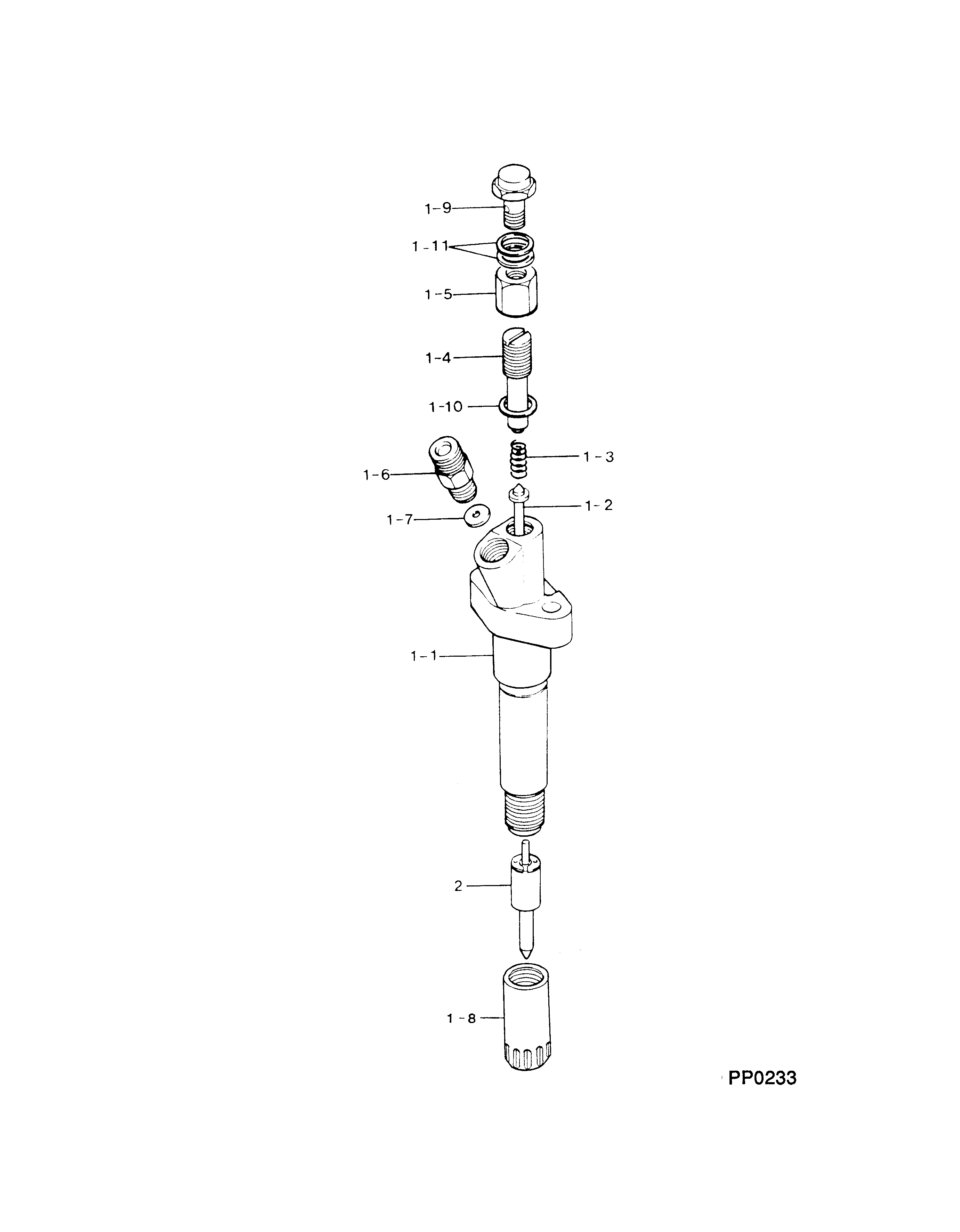
Injector Nozzle
Components :
Scheme #.#:
№
Qty
Part num
Name
Remarks
Manufacture num
000
[01]
09350-03310
HOLDER & NOZZLE SE
ME035527
MITSUBISHI
Include in ##:
09350-03310
as HOLDER & NOZZLE SE
Nozzle Specification:
Parts number
0935003310 MITSUBISHI
Nozzle
0934001920
First opm
22.05-22.83
First op
225-233
Second om
-
Second op
-
Torquen
58.8-78.4
Torque
6.0-8.0
Prelift
-
Max lift
Engine
TRUCK 6D14-W
Information
Include as Nozzle:
Cross reference number
Part num
Firm num
Firm
Name
09350-03310
ME035527
HOLDER & NOZZLE SE
0935003310
ME035527
MITSUBISHI
HOLDER & NOZZLE SE
Information:
Start By:a. remove oil pump1. Check the connecting rods and caps for their identification and location. 2. Turn the crankshaft until the connecting rod caps are in the position shown.3. Remove bolts (1) and the cap from the connecting rod. Remove the lower half of the bearing from the cap.4. Push the connecting rod away from the crankshaft. Remove the upper half of the bearing from the connecting rod. Install the bearings dry when the clearance checks are made. Put clean engine oil on the bearings for final assembly.5. Install the upper half of the bearing in the connecting rod.6. Put the connecting rod slowly on to the crankshaft.7. Install the lower half of the bearing in the cap. Be sure the tabs in the back of the bearings are in the tab grooves of the connecting rod and cap.The servicemen must be very careful to use Plastigage, tool (A) correctly. The following points must be remembered:...Make sure that the backs of the bearings and the bores are clean and dry....Make sure that the bearing locking tabs are properly seated in their slots....The crankshaft must be free of oil where the Plastigage touches it....Put a piece of Plastigage (A) on the crown of the bearing half that is in the cap. Do not allow the Plastigage to extend over the edge of the bearing....Install the bearing cap using the correct torque-turn specifications. Do not use an impact wrench. Be careful not to dislodge the bearing when the cap is installed....Do not turn the crankshaft with the Plastigage installed....Carefully remove the cap but do not remove the Plastigage. Measure the width of the Plastigage while it is in the bearing cap or on the crankshaft journal. Do this by using the correct scale on the package....Remove the Plastigage before reinstalling the cap.When using Plastigage, the readings can sometimes be unclear. For example, all parts of the Plastigage are not the same width. Measure the major widths to make sure that they are within the specification range. Also, experience has shown that when checking clearances tighter than 0.10 mm (.004") the readings may be low by 0.013 to 0.025 mm (.0005 to .0010"). Out-of-round journals can give faulty readings. Also, journal taper may be indicated when on end of the Plastigage is wider than the other.For complete details concerning measuring bearing clearances, see Engine Bearings And Crankshafts, Form No. SEBD0531. 8. Use Plastigage (A) to check the bearings clearance.9. Put Plastigage (A) on the bearing.10. Put 2P2506 Thread Lubricant on the threads of the rod bolts. Be sure the cylinder numbers on the rod cap and rod are the same and are on the same side of the connecting rod. Number are on the same side of the rod and cap as are the bearing tab slots. If new rods are installed, put the cylinder number on the rod and caps. Do not turn the crankshaft when the Plastigage (A) is in position. 11. Install rod caps (2). Install the