Rating:
Information holder & nozzle se Denso
Product
Nozzle & Nozzle Holder
Vehicle engine
INDUSTRIAL AD105
Engine
AD105
Serial start-end
7706-
Info
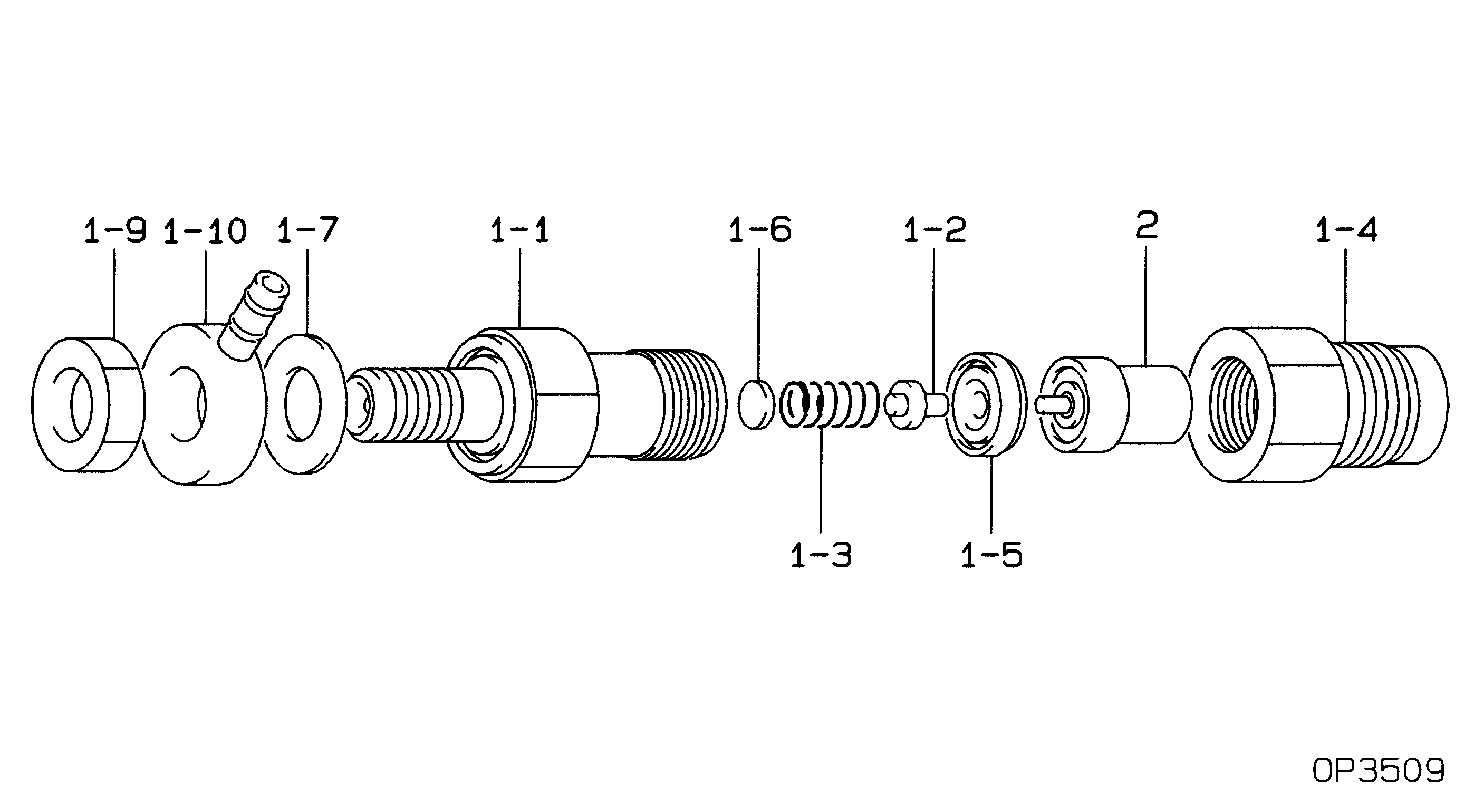
Injector Nozzle
Components :
Scheme #.#:
№
Qty
Part num
Name
Remarks
Manufacture num
000
[01]
09350-01330
HOLDER & NOZZLE SE
Include in ##:
09350-01330
as HOLDER & NOZZLE SE
Nozzle Specification:
Parts number
0935001330 MITSUBISHI
Nozzle
0934000340
First opm
11.76-12.74
First op
120-130
Second om
-
Second op
-
Torquen
58.8-78.4
Torque
6.0-8.0
Prelift
-
Max lift
Engine
INDUSTRIAL AD105
Information
Include as Nozzle:
Cross reference number
Part num
Firm num
Firm
Name
09350-01330
HOLDER & NOZZLE SE
Information:
START BY:a. remove fuel injection pump housing and governorb. remove fuel transfer pumpc. remove tachometer drive If it is desired to only remove the governor so the fuel injection pump housing can be disassembled, do only Steps 1, 2, 3, 16, 22, 25, 26, 27, 28, 32, 34 and 37. 1. Put the fuel injection pump housing and governor in position on tool (A).2. Remove the bolts, fuel ratio control (1) and shutoff solenoid (2) from rear governor housing (3).3. Remove the bolts, rear governor housing (3) and the gasket from the front governor housing. 4. Remove governor spring (4), the two wave washers, one flat washer and the seat from the guide in the rear governor housing. 5. Remove bolt (5) that holds lever assembly (6) to the shaft assembly. There is a key in the (slot) groove of the shaft assembly that must be removed before the shaft assembly is removed from the rear governor housing.6. Remove shaft assembly (7), lever (6) and lever (8) from the rear governor housing. Put an alignment mark on lever (9) for correct assembly purposes.7. Remove bolt (10), lever assembly (9) and spring (11) from shaft assembly (7). 8. Remove plug (12) and lip-type seal (13) from the housing. Spacers (14) and (16) are different sizes. Make sure they are assembled in the correct position.9. Use needle nose pliers, and remove the shaft. Remove spacer (14), lever (15) and spacer (16) from the governor housing. 10. Remove two setscrews and locknuts (17) if necessary. 11. Release spring (18) from the notch in the housing. Remove snap ring (19), and remove shaft (20) from the housing. Remove lever (21) and spring (18). 12. Remove lip-type seal (22) from the housing. 13. If necessary, remove the screws, cover (23) and the gasket from the governor housing. 14. Remove high idle cover (24) and three O-ring seals (25). 15. Remove lip-type seal (26), dashpot valve (27), fitting (25), insulator and high idle adjustment (28) from the rear housing. 16. Remove two bolts (29), housing (30) and the gasket from the fuel pump housing. 17. Remove bolts (31), and remove torque control group (32) from the block.
Depending on the different engine applications, torque control groups will vary. Inspect all parts for wear and damage, and make a note of the correct sequence of the parts for assembly purposes.
For additional information, see Specifications For 3406B Diesel Truck Engines. 18. Remove the bolts and block (33) for the full load stop from the housing. 19. Remove the bolt that holds collar (35) to bolt (36).20. Remove collar (35) and spring (34) from bolt (36). Remove bolt (36) from the block.21. If necessary, remove the stop screw and the power setting screw from collar (35). It may be necessary to turn the piston to remove the servo from the rack.22. Remove the three bolts and governor servo (37) from the fuel injection pump housing. 23. Remove lockring (43), seat (42), spring (41) and sleeve (40) from valve