Rating:
Information holder & nozzle se Denso
Product
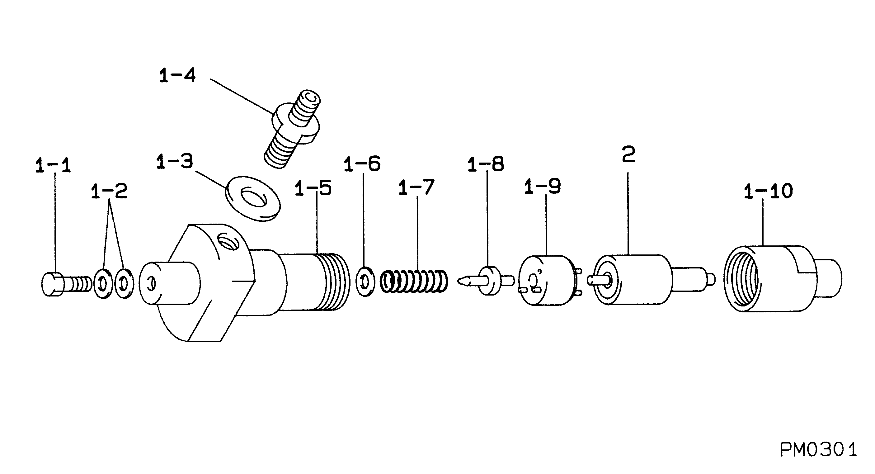
Nozzle & Nozzle Holder
Vehicle engine
INDUSTRIAL F/L912
Engine
F/L912
Serial start-end
8001-
Info
Injector Nozzle
Components :
Scheme #.#:
№
Qty
Part num
Name
Remarks
Manufacture num
000
[01]
09350-00990
HOLDER & NOZZLE SE
Include in ##:
09350-00990
as HOLDER & NOZZLE SE
Nozzle Specification:
Parts number
0935000990 MITSUI DEUTZ
Nozzle
0934000450
First opm
17.15-18.13
First op
175-185
Second om
-
Second op
-
Torquen
58.8-78.4
Torque
6.0-8.0
Prelift
-
Max lift
Engine
INDUSTRIAL F/L912
Information
Include as Nozzle:
Cross reference number
Part num
Firm num
Firm
Name
09350-00990
HOLDER & NOZZLE SE
Information:
1. Put gasket (2) in position. Make an alignment with the lever in the shutoff housing with the plunger in the fuel ratio control. control.2. Install fuel ratio control (1) and the bolts that hold it.Disassemble Fuel Ratio Control
start by:a) remove fuel ratio control1. Remove solenoid (1) from the fuel ratio control. 2. Remove bolts (3) and covers (2) and (4). Remove diaphragm (11) and piston (17). Remove gasket (16) from cover (4).
Spring force is present. Slowly loosen the two bolts to release the force.
3. Remove two bolts (5), cover (6) and spring (15).
Spring force is present. Hold diaphragm assembly in position and remove pin (14).
4. Remove pin (14) and slowly release the spring force.5. Remove spring (8) and bolt (7) from housing (12).6. Remove washer (10) and diaphragm (9) from retainer (13).Assemble Fuel Ratio Control
1. Assemble washer (3), diaphragm (2) and retainer (1).2. Install bolt (4) in housing (10).3. Install spring (5), diaphragm assembly (11) and pin (6) in housing (10).4. Install spring (22) in cover (7). Install cover (7) on housing (10) with the two bolts (16) that hold it. 5. Install gasket (13) on cover (8). Install piston (14) to cover (8). Install diaphragm (15) in cover (9). 6. Put covers (8) and (9) in position on cover (7) with the bolts that hold them.7. Install solenoid (17) on the fuel ratio control. end by:a) install fuel ratio control For adjustment of fuel ratio control, see TESTING AND ADJUSTING.