Rating:
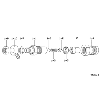
Information holder & nozzle se Denso
Product
Nozzle & Nozzle Holder
Vehicle engine
INDUSTRIAL D200
Engine
D200
Serial start-end
7301-
Info
Injector Nozzle
Components :
Scheme #.#:
№
Qty
Part num
Name
Remarks
Manufacture num
Nozzle Specification:
Parts number
0935000340 DAIHATSU
Nozzle
0934000060
First opm
10.29-11.27
First op
105-115
Second om
-
Second op
-
Torquen
58.8-78.4
Torque
6.0-8.0
Prelift
-
Max lift
Engine
Construction machine D200
Information
Include as Nozzle:
Cross reference number
Part num
Firm num
Firm
Name
09350-00340
HOLDER & NOZZLE SE
Information:
Disconnect all electrical power from the monitor before removing components. Failure to disconnect the power could result in severe electrical shock or damage to the monitor. An electrical shock can cause severe personal injury or death.
Components that are inside of the monitor may be damaged by Electrostatic Discharge (ESD). Make sure that you wear a grounding strap whenever you handle the following components: circuit boards, memory modules and other internal components.
Wear a well grounded wrist strap and perform work in a static free environment. Electrostatic discharge can damage the monitor and components.
In order to remove the back cover or the top cover, perform the following procedure:
Disconnect the power from the monitor.
Illustration 1 g00858068
(1) 4 Screws (2) 8 Screws
Loosen the 8 screws (2) that secure the back cover in place. Remove the screws in order to access the power supply, the hard drive, and the floppy disk drive.
Loosen the 4 screws (1) that secure the top cover. Remove the screws in order to access the add-in cards and the memory modules.
In order to reinstall the back cover, position the back cover over the chassis and tighten the 8 screws (2). Align the two pins on the inside of the back cover that secure the hard drive bay.Note: Be careful not to push the vibration dampers (grommets) on the drive out of the sheet metal.
In order to reinstall the top cover, position the top cover over the chassis and tighten the 4 screws (1) .
