Rating:
Information head sub-assy, dis Denso
Compare Prices: .
As an associate, we earn commssions on qualifying purchases through the links below

$362.33
17 Feb 2025
US: DMP Dependable Machi
VE Pump Rotor Head 4/11R 096400-1950 Fit Intended For
Generic spare parts || autoparts || machinery parts || engine parts
Generic spare parts || autoparts || machinery parts || engine parts

$96.99
05 Mar 2024
CN: Diesel Injection Par
Cabezales Fuel VE Pump Head Rotor 096400-1950 1950 4/11R Hydraulic Injection Pump Rotor Head 11MM 0964001950 Fits for Nissan Engine
Cabezales Manufacturer MFR No.:096400-1950 0964001950 Stamping No. 1950. || Application: Fit for Nissan Engine. || Package: 1 Piece of Pump Head Rotor.Neutral Packing. || Premium quality: Our Head Rotor Diesel Fuel Injection Pump Parts are made of high-quality materials, ensuring durability and longevity. || Notice:Please Check The No. Before Purchase Firstly,The Number Is Usually Stamped Around Its Body.If You Are Not Sure The No. Or You Have Any Question,Please Do Not Hesitate To Contact Us,We Will Reply You In Time.
Cabezales Manufacturer MFR No.:096400-1950 0964001950 Stamping No. 1950. || Application: Fit for Nissan Engine. || Package: 1 Piece of Pump Head Rotor.Neutral Packing. || Premium quality: Our Head Rotor Diesel Fuel Injection Pump Parts are made of high-quality materials, ensuring durability and longevity. || Notice:Please Check The No. Before Purchase Firstly,The Number Is Usually Stamped Around Its Body.If You Are Not Sure The No. Or You Have Any Question,Please Do Not Hesitate To Contact Us,We Will Reply You In Time.

$194.89
24 Oct 2024
KR: Adabus
Diesel engine high pressure plunger pump fuel head rotor 096400-1950
Generic Origin: FR(Origin)
Generic Origin: FR(Origin)
You can buy:

Include in ##:
Number on scheme 002

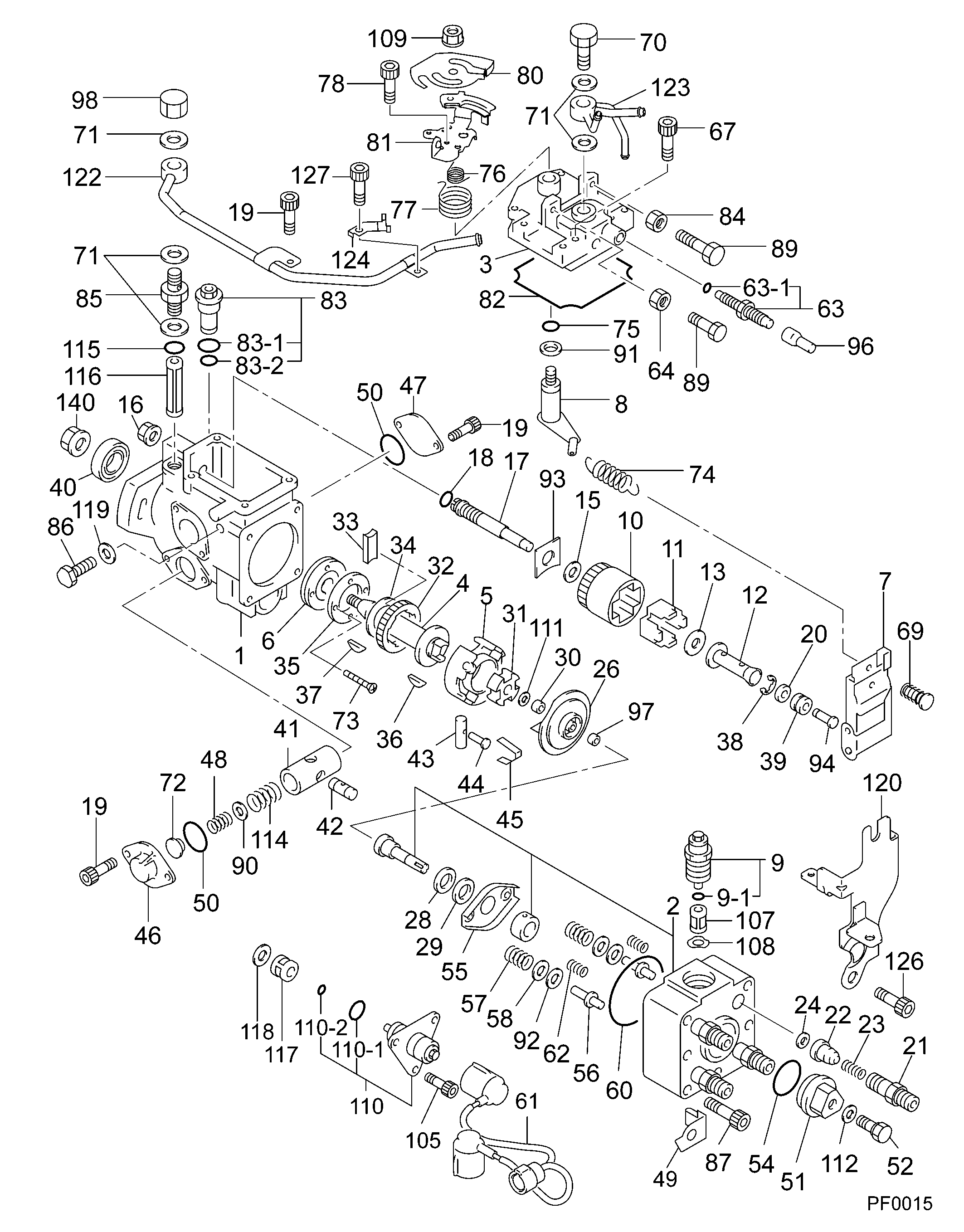
19600-05150
as HEAD SUB-ASSY, DIS
Cross reference number
Part num
Firm num
Firm
Name
09640-01950
HEAD SUB-ASSY, DIS
Information:
Introduction
This Special Instruction provides detailed instructions on the installation of the sleeve into the compensator group of the 3408E and 3412E Unit Injector Hydraulic Pump. If leaks are experienced at the joint of the compensator and the adapter block, the 174-8943 Sleeve may be installed to improve sealing. The new press fit sleeve contains the O-ring more securely than the original slip fit sleeve.Note: Engines built prior to the serial number break that contain the new sleeve have a "S" stamped at the end of the part number on the serial number plate of the pump. The reworked part numbers appear as "144-0835-06S". Individual Components
Table 1
Quantity Part Number Part Description
1 174-8943 Sleeve
1 135-2652 O-Ring
1 033-6039 O-Ring
6 9X-7680 O-Ring Necessary Tools
One of the following tools may be used to insert the new sleeve into the compensator group.
A 31.750 mm (1.250 inch) diameter flat plate.
The 1P-0467 Drive Plate from 1P-0510 Driver Group .
An acceptable bearing insertion tool.Removal Of The O-Ring Seals
Illustration 1 g00638376
Remove the four bolts (1) from the compensator (2). Remove the compensator and the adapter. Do not adjust the compensator. Refer to Special Instruction, REHS0192-03, step 3 of procedure for "Disassembly of the 144-0835 Unit Injector Hydraulic Pump Group ".
Illustration 2 g00638368
Remove the four O-ring seals (3) from the bottom side of the adapter. Refer to Special Instruction, REHS0192-03, step 4 of procedure for "Disassembly of the 144-0835 Unit Injector Hydraulic Pump Group ".
Illustration 3 g00638372
Remove the four O-ring seals (4) from the two housings. Refer to Special Instruction, REHS0192-03, step 5 of procedure for "Disassembly of the 144-0835 Unit Injector Hydraulic Pump Group ".
Remove the slip fit sleeve from the compensator housing.Installation Of The Sleeve
Illustration 4 g00637918
(1) Compensator assembly. (2) 174-8943 Sleeve .
Invert the compensator assembly (1). Hold the compensator assembly securely within a vise or a press table.
Start the sleeve (2) by hand into the compensator assembly (1) .Note: It is important that the groove on the outside diameter of the sleeve is oriented toward the O-ring in the joint. If this is not done, there will not be sufficient room to properly seal the O-ring.
Press the sleeve (2) flush with the surface of the compensator assembly (1) using the 1P-0467 Drive Plate or by using an acceptable bearing insertion tool.Installation Of The O-Ring Seals
Illustration 5 g00638368
Install the four O-ring seals (3) on the bottom side of the adapter. Refer to Special Instruction, REHS0192-03, step 16 of procedure for "Assembly of the 144-0835 Unit Injector Hydraulic Pump Group ".
Illustration 6 g00638372
Install the four O-rings (4) on the two housings. Refer to Special Instruction, REHS0192-03, step 17 of procedure for "Assembly of the 144-0835 Unit Injector Hydraulic Pump Group ".
Illustration 7 g00638376
Install the compensator assembly (2) and the adapter as a unit vertically so that the O-rings seals are not damaged. Tighten the four bolts (1) to the following torque.Torque for bolts ... 8 1 N