19080-05540 GOVERNOR ASSY, MEC Denso Cross


Rating:
23
Buy GOVERNOR ASSY, MEC 19080-05540 genuine, new aftermarket engine parts with delivery

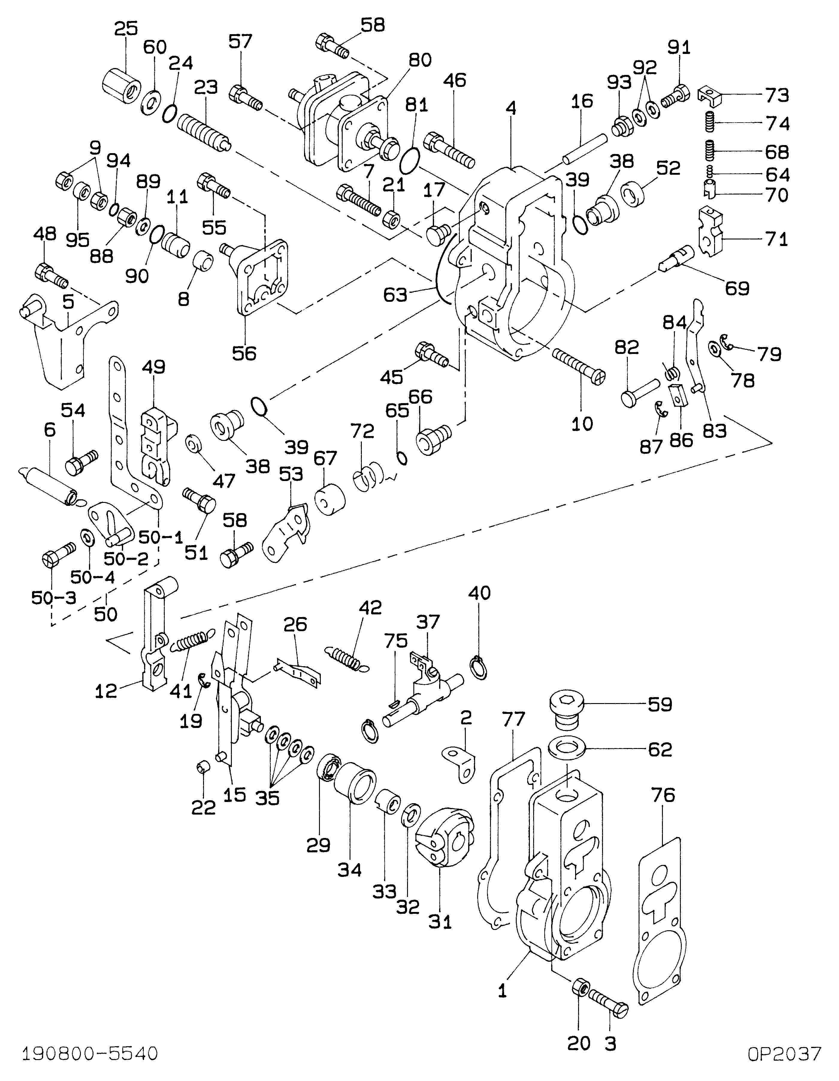
Information governor assy, mec Denso

KIT List:

Part name
Kit1
Kit2
Governor assy, mec
Governor assy, mec
Governor assy, mec

Scheme #.#:

Qty
Part num
Name
Remarks
Manufacture num
000
[01]
19080-05540
GOVERNOR ASSY, MEC
RSV
001
[01]
HOUSING SUB-ASSY,
002
[01]
PLATE
003
[01]
SCREW, ADJUSTING
004
[01]
COVER, GOVERNOR
005
[01]
ARM, SPRING
006
[01]
SPRING SUB-ASSY, R
007
[01]
SCREW, ADJUSTING
M8,L57
09102-40031 MITSUBISHI HEAEY INDUSTRIES
008
[01]
COLLAR, STEEL
-9901
009
[02]
NUT
010
[01]
SCREW, STROKE ADJU
011
[01]
BUSHING
-9901
09094-40310 MITSUBISHI HEAEY INDUSTRIES
011
[01]
BUSHING
9901-
012
[01]
LEVER, TENSION
015
[01]
LEVER ASSY, CONTRO
016
[01]
SHAFT, LEVER SUPPO
017
[01]
PLUG, SCREW
019
[01]
E-RING
020
[01]
NUT
M8,L19
021
[01]
NUT, HEXAGON, W/HO
M6
022
[01]
SLIDER, SUPPORTING
09104-60010 MITSUBISHI HEAEY INDUSTRIES
023
[01]
CAPSULE, FULL STOP
024
[01]
O-RING
ID9.8
025
[01]
NUT, ADAPTER LOCK
026
[01]
SHACKLE ASSY
029
[01]
BEARING, BALL
OD30
031
[01]
FLYWEIGHT ASSY
032
[01]
WASHER, SPRING
T2.5
033
[01]
NUT, ROUND
M12L12.5
034
[01]
SLEEVE, GOVERNOR
035
[4C]
WASHER, PLATE, SK
T0.2
035
[4C]
WASHER, PLATE, SK
T0.3
035
[4C]
WASHER, PLATE, SK
T0.4
035
[4C]
WASHER, PLATE, SK
T0.1
035
[4C]
WASHER, PLATE, SK
T1.0
037
[01]
LEVER ASSY, SWIEVE
038
[02]
BUSHING, LEVER
039
[02]
O-RING
ID15.8
040
[02]
WASHER, SNAP
ID15
041
[01]
SPRING, SPEED CONT
042
[01]
SPRING, START
045
[04]
BOLT, W/WASHER
M6,L40
94904-71760 MITSUBISHI HEAEY INDUSTRIES
046
[02]
BOLT, W/WASHER
M6,L50
94904-71750 MITSUBISHI HEAEY INDUSTRIES
047
[01]
SEAL, OIL
048
[03]
BOLT, W/WASHER
M6,L24
049
[01]
LEVER, ADJUSTING
050
[01]
LEVER SUB-ASSY, AD
050-001
[01]
LEVER, ADJUSTING
050-002
[01]
LEVER SUB-ASSY, AD
050-003
[02]
BOLT, W/WASHER
M8,L16
050-004
[01]
WASHER, COUPLING S
09241-70010 MITSUBISHI HEAEY INDUSTRIES
051
[01]
BOLT, W/WASHER
M6,L22
052
[01]
CAP, LEVER
09109-40060 MITSUBISHI HEAEY INDUSTRIES
053
[01]
LEVER SUB-ASSY, ST
054
[02]
BOLT, W/WASHER
M6,L16
91418-06161 MITSUBISHI HEAEY INDUSTRIES
055
[01]
BOLT, W/WASHER
M6,L20
056
[01]
PLATE SUB-ASSY, CO
057
[02]
BOLT, W/WASHER
M6,L14
94904-71790 MITSUBISHI HEAEY INDUSTRIES
058
[03]
BOLT, W/WASHER
M6,L14
91418-06141 MITSUBISHI HEAEY INDUSTRIES
059
[01]
PLUG, SCREW
09116-70050 MITSUBISHI HEAEY INDUSTRIES
060
[01]
WASHER, AIR BLEEDE
T1.6
MM500486 MITSUBISHI HEAEY INDUSTRIES
062
[01]
WASHER, COPPER PLA
T1.5
063
[01]
PACKING, RUBBER PL
064
[01]
SPRING, B
OD3.6
09103-80040 MITSUBISHI HEAEY INDUSTRIES
065
[01]
O-RING
ID9.0
066
[01]
BUSHING, BEARING
-9707
066
[01]
BUSHING, BEARING
9707-
067
[01]
COVER, SPRING
068
[01]
SPRING, B
OD6.6
09103-80050 MITSUBISHI HEAEY INDUSTRIES
069
[01]
SHAFT, MECHANICAL
09103-50240 MITSUBISHI HEAEY INDUSTRIES
070
[01]
CUP, SPRING
071
[01]
LEVER, SUPPORT
09103-40130 MITSUBISHI HEAEY INDUSTRIES
072
[01]
SPRING, RETURN
073
[01]
PLATE, CAP
09103-30030 MITSUBISHI HEAEY INDUSTRIES
074
[01]
SPRING, B
OD8.6
09103-80030 MITSUBISHI HEAEY INDUSTRIES
075
[01]
KEY, WOODRUFF
076
[01]
GASKET, PUMP BODY
077
[01]
GASKET
078
[01]
WASHER, PLATE
T0.5
079
[01]
E-RING
D5
080
[01]
COMPENSATOR SUB-AS
081
[01]
O-RING
ID26.2
082
[01]
PIN
083
[01]
LEVER SUB-ASSY, CO
084
[01]
SPRING, RETURN
086
[01]
BUSHING
087
[01]
E-RING
088
[01]
NUT
089
[01]
WASHER, COPPER PLA
T1
090
[01]
O-RING
ID12.3
091
[01]
SCREW, HOLLOW
092
[02]
WASHER, DRAIN SCRE
T1.0
093
[01]
NIPPLE
094
[01]
O-RING
ID5.8
095
[01]
COLLAR, STEEL

Include in ##:

09200-02610 as GOVERNOR ASSY, MEC
19080-05540 GOVERNOR ASSY, MEC

Cross reference number


Part num
Firm num
Firm
Name
19080-05540 
 
GOVERNOR ASSY, MEC


Information:


Illustration 1. 173-1530 Injector Seating Tool Group. See Chart A for item identification and part numbers. MUI Engine Procedure
This procedure can be used for 3114, 3116, and 3126 MUI Engines.1. Install a new injector brass sleeve or inspect and ream the existing sleeves as outlined in Tool Operating Manual NEHS0675. It is not necessary to ream new sleeves when using this procedure.2. Install the unit injector and align the rack bar. Do not use the small O-ring on the injector tip.3. Install holding clamp bolt (12) and tighten to 12 3 N m, 1.2 0.3 meter kg, (9 2 lb. ft.).
Illustration 2. Install Holding Clamp Bolt (12).4. Remove inlet manifold bolt (13) closest to the injector.
For a repair procedure, remove only one manifold bolt at a time. Removing all the manifold bolts could weaken or damage the manifold/head gasket material.
Illustration 3. Remove Inlet Manifold Bolt (13).5. Install MUI injector forcing cover (7) over the injector. The milled surface should line up with injector clamp bolt. The two long flat surfaces are for valve spring clearance. Refer to the "MUI Tooling" section for a warning on the sharp edges of this tool.
Make sure the slots of injector forcing cover (7) are free of nicks, scratches, or burrs. Damage in the slots will result in damage to the injector spring.
Illustration 4. Install Injector Forcing Cover.
Illustration 5. MUI Injector Forcing Cover Properly Installed.6. If assembled, back out forcing bolt (4) in forcing bridge (1) to provide clearance between the injector forcing cover and forcing bridge.7. Place a small amount of 4C-5591 Thread Lubricant on top of the injector forcing cover's wear button (10) and on the threads of forcing bolt (4).
Complete lubrication of the wear button and forcing bolt must be maintained for each injector seating procedure. Failure to relubricate each part before seating the next injector may cause premature wear or tool damage. Also, make sure the forcing bolt turns freely and does not have any damaged threads.
8. Install the forcing bridge with three 7X-0457 Bolts (5) and three 9M-1974 Hard Washers (6). Put the two long legs of the forcing bridge in the two rocker arm shaft support holes closest to the injector. The short leg of the forcing bridge with spacer (2) installed sits on the intake manifold bolt boss. [The long spacer (3) is used when the manifold is not installed.]
Illustration 6. Install Forcing Bridge.(1) MUI Forcing Bridge.(2) Short spacer leg.(5) 7X-0457 Hex Head Bolt.(6) 9M-1974 Hard Washer
Do not install the injectors "off-engine" because the injector tip will protrude from the head and be subject to damage. If the injectors are installed off-engine, make sure the bottom surface of the head is raised off the surface of the work bench.
9. Tighten forcing bridge mounting bolts (5) to 28 7 N m, 2.9 0.7 meter kg, (21 5 lb. ft.).
Damage to the head could occur if bridge mounting bolts (5) are not tightened to the specified torque.
Illustration 7. Install Forcing Bolt (4).10.

Have questions with 19080-05540?


Group cross 19080-05540

Back to top