Rating:
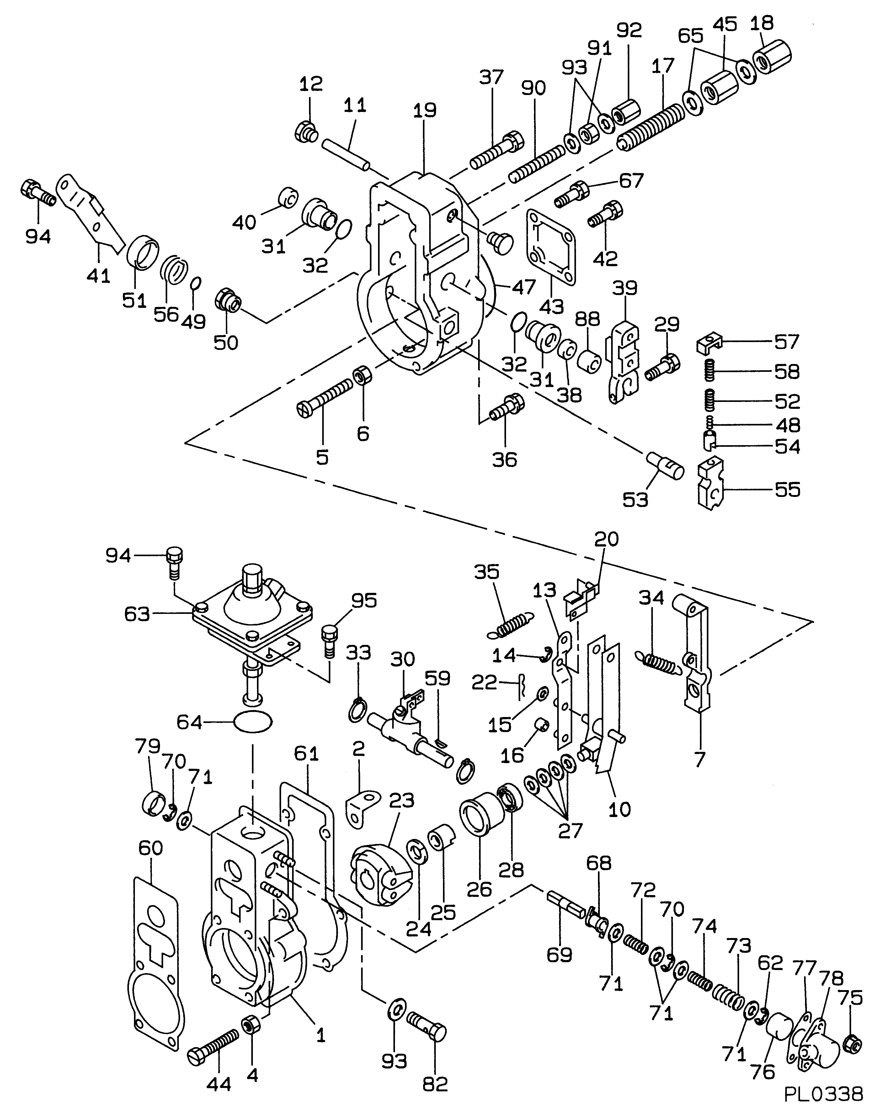
Information governor assy, mec Denso
Scheme #.#:
№
Qty
Part num
Name
Remarks
Manufacture num
000
[01]
19080-02941
GOVERNOR ASSY, MEC
RSVH
Include in ##:
Cross reference number
Part num
Firm num
Firm
Name
19080-02941
GOVERNOR ASSY, MEC
Information:
Introduction
This Special Instruction provides the removal procedure and the installation procedure for the HEUI Injector.
The correct procedures and tooling specifications must always be used. Failure to follow any of the procedures may result in damage, malfunction, or possible engine failure.
Keep all parts clean from contaminants.Contaminants may cause rapid wear and shortened component life.
Care must be taken to ensure that fluids are contained during performance of inspection, maintenance, testing, adjusting and repair of the product. Be prepared to collect the fluid with suitable containers before opening any compartment or disassembling any component containing fluids.Refer to Special Publication, NENG2500, "Caterpillar Tools and Shop Products Guide" for tools and supplies suitable to collect and contain fluids on Caterpillar products.Dispose of all fluids according to local regulations and mandates.
The injector is not serviceable. The warranty and/or the core credit for remanufacturing may be reduced for the following reasons:
Disassembling or tampering with the injector
Not returning the injector in the original protective packaging
Damaging the injector during removal or installationNote: An injector with possible damage to the tip must be returned in the original package. The damaged injector must be clearly identified as having possible tip damage.
The injector tip was made very hard to provide a long life. This hardness also makes the tip brittle. Side loading during the installation or striking the tip against a hard object or dropping the injector can cause the tip to break or crack. Installing an injector with a cracked tip may result in major engine damage.
Table 1
Required Tools
Tool Part Number Part Description Qty
A 149-2955 Seal Protector 1
B 149-2956 Seal Installer 1
C 152-1057 Fuel Injector Installer As 1
D 1U-7588 Pry Bar 1 Tools For Cleaning Carbon Deposits From The Injector Sleeve Bores
4C-5027 Tap Wrench
4C-6161 Tube Brush
4C-6774 Vacuum Gun Kit
8T-7765 Surface Reconditioning Pad
1U-5512 Cut & Polish Roll
9U-6102 Reamer
9U-6862 Tapered Brush Tools For Evacuating Fuel From The Cylinders
4C-4057 Tube
1U-5718 Vacuum Pump
1U-5814 Bottle Assembly Removal Of The Injector
Illustration 1 g00293685
(1) 128-6601 Solenoid Assembly (2) Harness Connector (3) Clamp (4) O-Ring Seals (5) 9Y-9025 Sleeve (6) Angled Seat (7) 137-5621 Tip Assembly
Remove the valve cover assembly.
Illustration 2 g00777907
(8) Oil Drain Plug
Remove oil drain plugs (8) at each end of the cylinder head.
Illustration 3 g00778847
(2) Wiring Harness Connection (3) Clamp (9) Injection Actuation Pressure Sensor (10) Shoulder Bolt (11) Socket Head Bolt
Remove the Injection Actuation Pressure Sensor (9) .
Allow the engine oil to drain from the ports in the cylinder head before the injector is removed.
Remove the harness connector (2) away from the injector solenoids.
Remove the Shoulder Bolt (10) and the Socket Head Bolt (11) from the clamp (3) .
Illustration 4 g00294212
Illustration 5 g00778851
(12) Do not pry here. (13) Tool (D) should be placed at this location in order to gently remove the injector.
Place Tool (D) under the clamp (13) on the flywheel side of the injector.
Use Tool (D)