Rating:
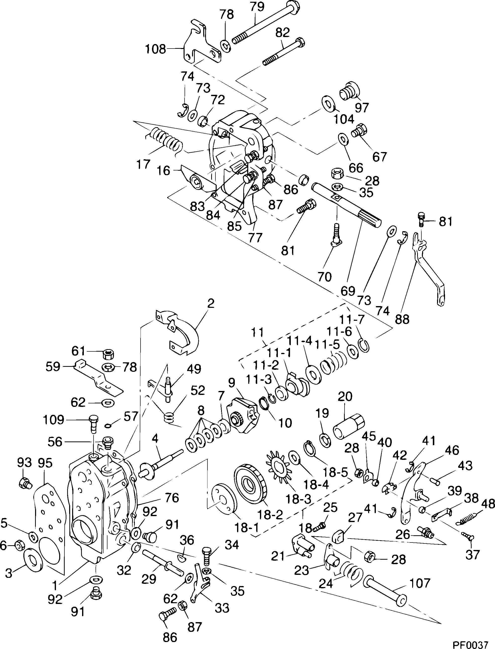
Information governor assy, mec Denso
Scheme #.#:
№
Qty
Part num
Name
Remarks
Manufacture num
000
[01]
19080-02062
GOVERNOR ASSY, MEC
RUV
Include in ##:
19080-02062
as GOVERNOR ASSY, MEC
Cross reference number
Part num
Firm num
Firm
Name
19080-02062
GOVERNOR ASSY, MEC
Information:
1. Disconnect wires (1) from the Jake Brake. Remove three bolts (2) and two nuts (3). Remove the Jake Brake. 2. Remove the Jake Brake exhaust bridge assemblies (4). The following steps are for the installation of the Jake Brake.3. Put Jake Brake exhaust bridge assemblies (4) in the same positions shown in Photo C52074P1.4. Position the Jake Brake assembly, and install three bolts (2) and two nuts (3) that hold it. Tighten three bolts (2) to a torque of 55 10 N m (41 7 lb ft). Tighten two nuts (3) to a torque of 80 15 N m (59 11 lb ft).5. Connect wires (1) to the Jake Brake.End By:a. install valve cover assembliesDisassemble & Assemble Jake Brake
Start By:a. remove Jake Brake (An Attachment) 1. Apply finger pressure to control valve cover (6). Remove retaining ring (7). Release finger pressure slowly. Remove control valve cover (6), insert (5), spring (4), spring (3), collar (2) and control valve (1). 2. Remove solenoid (8). Remove three O-ring seals (9) from the solenoid. 3. Remove locknut (11). Back out adjusting screw (10) until the slave piston is fully retracted. 4. Using a suitable size clamp, compress retainer (15) until it is 1mm (.039 in) below the retaining ring groove. Using suitable size snap ring pliers, remove retaining ring (16). Slowly loosen the clamp to release the spring pressure against retainer (15), springs (14) and (13) and slave piston (12). 5. Using suitable snap ring pliers, remove retaining ring (20). Remove retainer (19), spring (18) and master piston assembly (17). The following steps are for the assembly of the Jake Brake.6. Check the condition of the master piston assembly (17). The master piston assembly must be free of score and wear marks.7. Install master piston assembly (17), spring (18), retainer (19) and retaining ring (20).8. Install slave piston (12), springs (13) and (14) and retainer (15). Clamp and compress and slave piston retainer until it is 1 mm (.039 in) below the retaining ring groove. Install retaining ring (16). Release the clamp. Be sure retainer (15) is seated properly.9. Screw adjusting screw (10) in until it makes contact with the slave piston. Install locknut (11) on the screw.
Be sure O-ring seals (9) are seated on solenoid (8). Do not twist or unseat the O-ring seals during installation of the solenoid.
10. Check the condition of the O-ring seals (9) used on solenoid (8). If the seals are worn or damaged, use new parts for replacement. Install three O-ring seals (9) on solenoid valve (8). Install solenoid valve (8), and tighten it to a torque of 7 N m (60 lb in).11. Install control valve (1). Install collar (2) with the longer sleeve area facing up. Install springs (3) and (4) and insert (5). Install control valve cover (6). Install retaining ring (7). Rotate the retaining ring so the retaining ring ears are located away from the slot in the housing. Release finger pressure. For assembly adjustments of