Rating:
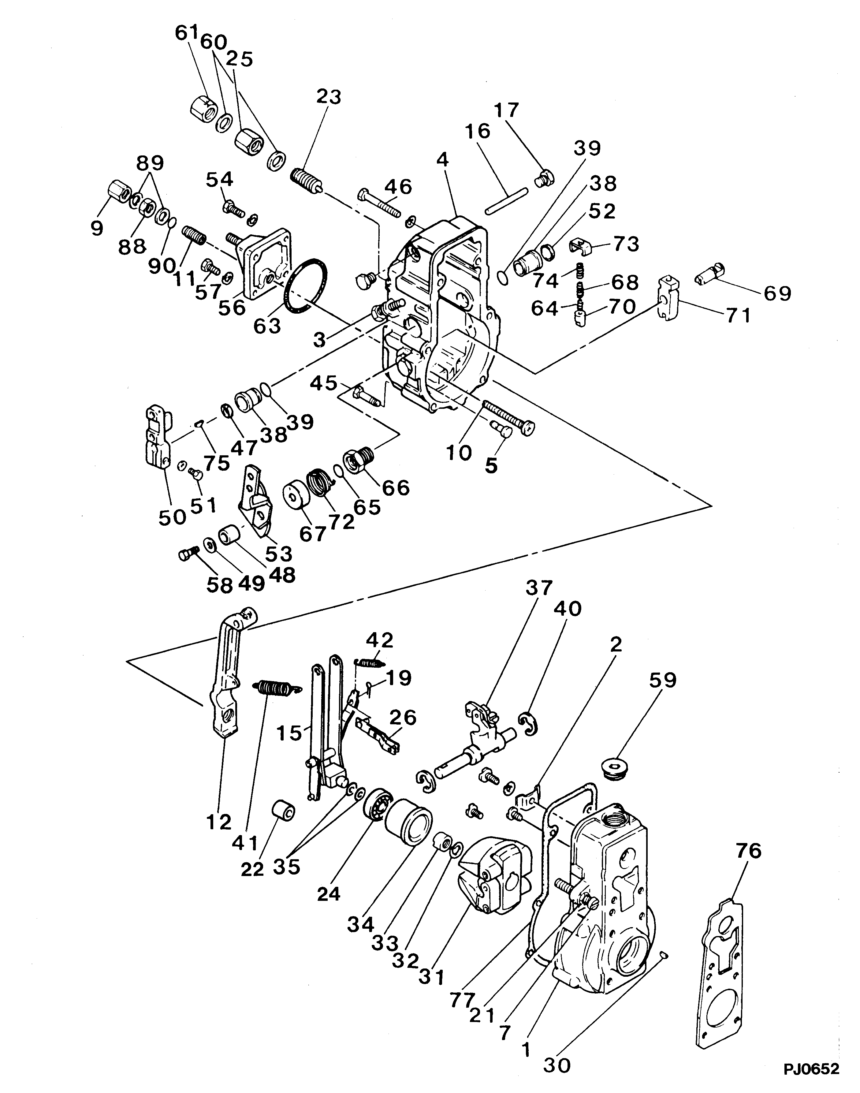
Information governor assy, mec Denso
KIT List:
Scheme #.#:
№
Qty
Part num
Name
Remarks
Manufacture num
000
[01]
19080-01670
GOVERNOR ASSY, MEC
RSV
Include in ##:
Cross reference number
Part num
Firm num
Firm
Name
19080-01670
GOVERNOR ASSY, MEC
Information:
1. Use tool (A) to remove the engine oil filter. 2. Remove bolts (1) and the washers that hold the tube to the oil pump elbow. Remove bolts (2) and the washers that hold oil pump elbow (3) to the cylinder block. 3. Remove four bolts (4) and the washers that hold the engine oil pump to the front housing. Remove the engine oil pump and the oil pump elbow as a unit. The following steps are for the installation of the engine oil pump.4. Check the condition of the O-ring seal used at the tube-to-oil pump elbow connection and the O-ring seal used on the engine oil pump. If the seals are worn or damaged, use new parts for replacement.5. Install the O-ring seal in the oil pump elbow. Install the O-ring seal on the engine oil pump. Lubricate the bore in the front housing with clean engine oil. Put the engine oil pump in position in the front housing.6. Install four bolts (4) and the washers that hold the engine oil pump to the front housing.7. Install two bolts (2) and the washers that hold the oil pump elbow to the cylinder block.8. Install two bolts (1) and the washers that hold the tube to the oil pump elbow.9. Install the engine oil filter. Follow the instructions with the oil filter assembly for correct installation.Disassemble & Assemble Engine Oil Pump
Start By:a. remove engine oil pump 1. Remove oil pump elbow (1) from the engine oil pump. Remove the two O-ring seals from the oil pump elbow. Remove four bolts (2) and the washers. Remove cover (3) from the pump housing. 2. Remove O-ring seal (4) and idler gear (5) from the cover.3. Using tool (A), remove gear (6) from the drive shaft.
Before removing drive shaft (7) from the pump housing, be sure no burrs exist on the drive shaft. If the drive shaft has burrs, it may scratch the bores in the pump housing.
4. Remove drive shaft (7) from the pump housing. The following steps are for the assembly of the engine oil pump.5. Be sure all parts of the engine oil pump are thoroughly clean prior to assembly. Check the condition of the O-ring seals used in the engine oil pump and on the oil pump elbow. If the seals are worn or damaged, use new parts for replacement. Lubricate all internal parts of the engine oil pump with clean engine oil. 6. Install drive shaft (7) in the pump housing. Heat gear (6) to a maximum temperature of 316°C (601°F). Install gear (6) on the end of drive shaft (7). Position the gear so the distance between the outside face of the gear and the step face on the pump body is 29.40 0.50 mm (1.157 .020 in).7. Install idler gear (5) in the pump housing.8. Install O-ring seal (4) in cover (3). Install cover (3) and four bolts (2) and the washers that hold it. 9. Install the two O-ring seals