19080-01631 GOVERNOR ASSY, MEC Denso Cross


Rating:
56
Buy GOVERNOR ASSY, MEC 19080-01631 genuine, new aftermarket engine parts with delivery

Information governor assy, mec Denso

Scheme #.#:

Qty
Part num
Name
Remarks
Manufacture num
000
[01]
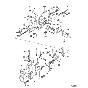
GOVERNOR ASSY, MEC
RSV -8810
000
[01]
19080-01631
GOVERNOR ASSY, MEC
8811-
001
[01]
HOUSING SUB-ASSY,
002
[01]
PLATE
003
[02]
SCREW, ADJUSTING
004
[01]
OVER-HAUL KIT, GOV
G/V COVER KIT
005
[01]
JOINT, FORK
006
[01]
PIN, STOP
009
[01]
NUT, CAP
010
[01]
SCREW, STROKE ADJU
011
[01]
BUSHING
012
[01]
LEVER, TENSION
-9404
012
[01]
LEVER, TENSION
9404-
015
[01]
LEVER ASSY, CONTRO
L/R:1.2
016
[01]
SHAFT, LEVER SUPPO
017
[02]
PLUG, SCREW
019
[01]
E-RING
021
[02]
NUT, HEXAGON, W/HO
022
[01]
SLIDER, SUPPORTING
023
[01]
CAPSULE, FULL STOP
025
[01]
NUT, ADAPTER LOCK
026
[01]
SHACKLE ASSY
030
[01]
KEY, WOODRUFF
031
[01]
FLYWEIGHT ASSY
032
[01]
WASHER, SPRING
T2.5
033
[01]
NUT, ROUND
034
[01]
SLEEVE SUB-ASSY, F
034-001
[01]
PLATE, THRUST
034-002
[01]
RING, HOLE SNAP
OD30
035
[C]
WASHER, PLATE, SK
T0.2
035
[C]
WASHER, PLATE, SK
T0.3
035
[C]
WASHER, PLATE, SK
T0.4
035
[C]
WASHER, PLATE, SK
T0.1
035
[C]
WASHER, PLATE, SK
T1.0
037
[01]
LEVER ASSY, SWIEVE
-9103
037
[01]
LEVER ASSY, SWIEVE
9103-
038
[02]
BUSHING, LEVER
-8904
038
[02]
BUSHING, LEVER
8904--9212
038
[02]
BUSHING, LEVER
9212-
039
[02]
O-RING
ID15.8 -8806
039
[02]
O-RING
8807-
040
[02]
WASHER, SNAP
041
[01]
SPRING, SPEED CONT
042
[01]
SPRING, START
043
[01]
ADAPTER ASSY
043-001
[01]
SCREW, ADPTER
043-002
[01]
ADAPTER
043-003
[01]
SPRING, MECHANICAL
043-004
[01]
SPRING, MECHANICAL
043-005
[C]
WASHER, PLATE, SK
T0.1
043-005
[C]
WASHER, PLATE, SK
T0.2
043-006
[C]
WASHER, PLATE, SK
T0.3
043-006
[C]
WASHER, PLATE, SK
T0.1
044
[01]
NUT, ADAPTER LOCK
045
[04]
BOLT, W/WASHER
M6,L40
046
[02]
BOLT, W/WASHER
M6,L50
047
[01]
SEAL, OIL
-8810
047
[01]
SEAL, OIL
8811-
049
[01]
LEVER, ADJUSTING
050
[01]
LEVER, ADJUSTING
051
[01]
BOLT, W/WASHER
M6,L22
052
[01]
CAP, LEVER
054
[02]
BOLT, W/WASHER
M6,L14
056
[01]
PLATE, COVER
057
[02]
BOLT, W/WASHER
M6,L14
058
[02]
BOLT, W/WASHER
M6,L16
059
[01]
SCREW,PLUG
060
[02]
WASHER, AIR BLEEDE
061
[01]
NUT, CAP
063
[01]
PACKING, RUBBER PL
-8806
063
[01]
PACKING, RUBBER PL
8807--9005
063
[01]
PACKING, RUBBER PL
9005-
075
[01]
KEY, WOODRUFF
076
[01]
GASKET, PUMP BODY
-9304
076
[01]
GASKET, PUMP BODY
9305-
077
[01]
GASKET
-9305
077
[01]
GASKET
9306-
086
[01]
BUSHING
8807-
087
[C]
WASHER, PLATE, SK
T0.3 8807-
087
[C]
WASHER, PLATE, SK
T0.6 8807-
087
[C]
WASHER, PLATE, SK
T0.9 8807-
088
[01]
NUT, HEXAGON
M8 -9503
088
[01]
NUT, HEXAGON
M8 9504-
089
[02]
WASHER, COPPER PLA
T1
090
[01]
O-RING
ID12.3 -8806
090
[01]
O-RING
8807-
091
[01]
SCREW, HOLLOW
092
[02]
WASHER, FUEL PIPE

Include in ##:

19080-01631 as GOVERNOR ASSY, MEC

Cross reference number


Part num
Firm num
Firm
Name
19080-01631 
 
GOVERNOR ASSY, MEC


Information:

(4) Spacer block.(5) Height of dowels above top surface of spacer block and cylinder block ... 8.00 0.03 mm (.315 .001 in)(6) Cylinder Liner. Make reference to the procedure for checking Cylinder Liner Projection in Testing And Adjusting Section of Service Manual Form No. SENR5561.Cylinder liner projection above the top surface of the spacer block must be ... 0.12 0.08 mm (.005 .003 in)Apply 7M7260 Liquid Gasket as required to cylinder liner shoulder and cylinder block face joint of all liners. (7) Depth plug is to be installed (from end surface of cylinder block to top of plug) ... 1.25 0.25 mm (.049 .010 in)(8) Diameter of camshaft bores ... 75.000 0.025 mm (2.9530 .0010 in)(9) Oil cooling jet assembly. Tighten bolt that holds oil cooling jet to ... 25 7 N m (18 5 lb ft)(10) Width of main bearing cap ... 175.00 0.02 mm (6.8898 .0008 in) Width in cylinder block for main bearing cap ... 175.000 0.018 mm (6.8898 .0007 in)(11) Distance from centerline of crankshaft bore to top surface of cylinder block ... 265.0 mm (10.43 in)The flatness across the top contact surface of the block must be within 0.05 mm (.002 in) for any 150 mm (5.9 in) section of the surface.(12) Distance from centerline of crankshaft to bottom surface of cylinder block ... 120.0 mm (4.72 in)(13) Main bearing cap bolts. Install as follows: Main bearing caps shall be assembled with the part number towards the right side. Caps are to be identified by stamped numbers 1 through 7 located on the bottom unmachined surface.Main bearing cap bolts to be lubricated on threads and washer face with SAE 30 oil or molylube. Tighten bolts to 95 5 N m (70 4 lb ft) plus 90 5 degrees additional turn prior to machining. Tighten bolts simultaneously or tighten both bolts to 95 N m (70 lb ft) before turning the additional 90 degrees.(14) Bore in cylinder block for seven main bearings ... 108.000 0.013 mm (4.2520 .0005 in) All main bearing bore measurements are to be made before caps are disassembled.
Have questions with 19080-01631?


Group cross 19080-01631

Back to top