Rating:
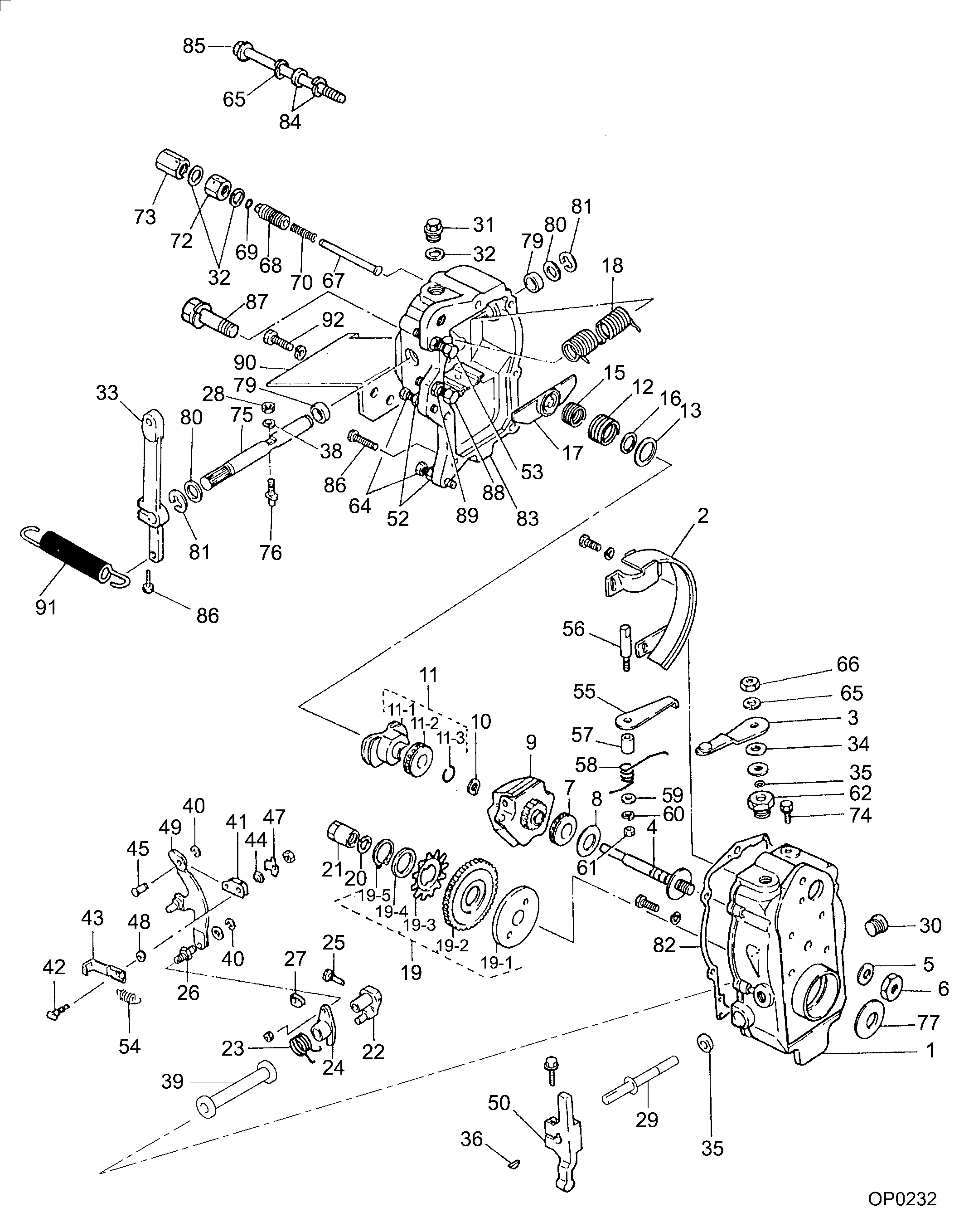
Information governor assy, mec Denso
KIT List:
Scheme #.#:
№
Qty
Part num
Name
Remarks
Manufacture num
000
[01]
19080-00990
GOVERNOR ASSY, MEC
RUV
-9011
Include in ##:
Cross reference number
Part num
Firm num
Firm
Name
19080-00990
GOVERNOR ASSY, MEC
Information:
1. Disconnect plug P14 from receptacle J14. The locking ring helps identify P14 from J14. Check the connections for damaged wires or pins and corrosion. Also check that the pins are at the proper height in the connector. Check that the wires and pins are tight in the connectors by pulling (slightly) on each wire of each connector (including the breakout "T").2. Install 8T8694 Adapter (five pin breakout "T") between J14 and P14. Twist the locking rings to secure the connections.3. Connect the voltmeter as shown. Check for the appropriate voltages between the lettered "T" pins as explained in Steps 4 through 7.4. Pin A (+) to pin B (ground) system voltage should be approximately 12 volts DC with key on (no accessories). Minimum voltage is 11.0 volts DC. Diagnosis - Using the truck wiring schematic, check wires A and B and connections from J14 through the truck wiring harness back to the battery for proper voltage.5. If the voltage check between pins A and B is less than 11.0 volts with the key on, check the voltage drop from pin B to the negative battery post while cranking. For this test, the common lead (black) should be connected to the negative battery post first. Then place the positive (red) lead into pin B. (Pin B is chassis ground.) Voltage should be less than .5 volts DC when cranking. Diagnosis - If the voltage drop is greater than .5 volts DC, check wire B and connections (including the battery post connections) from J14 to battery negative. Follow the truck wiring schematic to trace the electrical path from J14 to chassis ground. Step 6 checks the proper functioning of the truck wiring, vehicle speed sensor and vehicle speed buffer. If proper vehicle speed is present on the appropriate status screens of the 3176 (7X1055) DDT or the (8T8697) ECAP service tools during road test than Step 6 is not necessary.6. Pin C to pin B:* 0 volts when stopped.* Up to 2.3 volts DC with the transmission output shaft turning and the speedometer disconnected (open circuit).
Remove the axle shafts or disconnect the drive shaft from the transmission to perform this test. See the truck manufacturer's instructions for the correct procedure(s).
Diagnosis: Remove magnetic pickup (vehicle speed sensor) from transmission. If pickup has collected significant metal debris, wipe it clean. Check the magnetic pickup per the manufactures specifications. Install a properly functioning magnetic pickup to the proper depth and reconnect to the vehicle speed buffer. Repeat Step 6. The problem may reappear if transmission fluid is contaminated. Change transmission fluid if necessary.* Check wires and connectors for damage or corrosion from the magnetic pickup to vehicle speed buffer.* Replace vehicle speed buffer (Caterpillar supplied part).
Vehicle Speed Buffer (1) Magnetic Pickup (2) in transmission.7. Pin D to pin B (static check):* Disconnect the magnetic pickup (in transmission) from the input wires of the vehicle speed buffer. With the key on, the voltage should be 4.5-7.5 volts DC. Diagnosis - If the voltage