Rating:
Information governor assy, mec Denso
MITSUBISHI
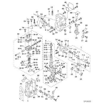
GOVERNOR ASSY, MEC
EA
- *1 WHEN REPLACING A CAM PLATE, SELECT THE SPECIFIED
- GUIDE ARM TO MATCH THE MARK.
KIT List:
Scheme #.#:
№
Qty
Part num
Name
Remarks
Manufacture num
Include in ##:
Cross reference number
Part num
Firm num
Firm
Name
09130-03410
MITSUBISHI
GOVERNOR ASSY, MEC
Information:
1. Remove the retaining ring (1) and pin (2). 2. Remove the seat (3), bolt (4), washers (5), and spring (6).3. Remove the sleeve and bearing assembly from the cylinder and weight assembly. 4. Remove the retaining ring (7) from sleeve (8).5. Remove the bearing (9) and races (10) from sleeve (8). 6. Remove the valve (11) from piston (12).7. Remove the retaining ring (13) from the cylinder and weight assembly.8. Remove the weight assembly (14).9. Remove piston (12) and sleeve (15) from the cylinder (16).10. Remove the O-ring seal from sleeve (15). 11. Remove the speed limiter plug (17), spring (18), and plunger (19) from the governor housing.12. Remove the high idle screw (21) and low idle screw (20). 13. Remove the bolt and lock that holds the shaft (22) to lever assembly (23).14. Remove the shaft (22) and lever assembly (23) from governor housing.15. Remove the seal and bearings from governor housing. 16. Remove the two bolts (25) and lock. Remove the lever (24) and shaft (26) from idle screw housing.17. Remove the two seals and bearing from idle screw housing.Assemble Governor
1. Install the O-ring seal (3) on sleeve (4).2. Install piston (2) and sleeve (4) in the cylinder (1). 3. Put the weight assembly (6) in position on cylinder (1), and install retaining ring (5). 4. Install valve (8) in piston (2).5. Install the bearing and races in sleeve. Install the retaining ring. Install the sleeve and bearing assembly (7) on valve (8). 6. Put the bolt (10), washers (11), and spring (12) in position in seat (9). 7. Put the holes in seat (9), sleeve and bearing assembly (7), and valve (8) in alignment, and install the pin (13). Install the retaining ring (14). 8. Use tool setup (A) to install the inner seal in idle screw housing with the spring side of seal toward tool setup (A). Use tool setup (A) to install the outer seal in housing with lip of seal toward inside of housing. Put clean oil on the bearing and lip of seals.9. Put the shaft and lever in position in the idle screw housing, and install the bolts and lock. 10. Install the two bearings in governor housing. Use tool setup (A) to install the seal in housing with lip of seal toward inside of the governor housing. Put clean oil on the bearings and lip of seal. 11. Put the shaft (15) and lever assembly (17) in position in governor housing, and install the bolt (16) and lock. Install the high and low idle screws in housing. Install the speed limiter plunger, spring, and plug in housing.end by: a) connection of governor to fuel injection pump housing
1. Install the O-ring seal (3) on sleeve (4).2. Install piston (2) and sleeve (4) in the cylinder (1). 3. Put the weight assembly (6) in position on cylinder (1), and install retaining ring (5). 4. Install valve (8) in piston (2).5. Install the bearing and races in sleeve. Install the retaining ring. Install the sleeve and bearing assembly (7) on valve (8). 6. Put the bolt (10), washers (11), and spring (12) in position in seat (9). 7. Put the holes in seat (9), sleeve and bearing assembly (7), and valve (8) in alignment, and install the pin (13). Install the retaining ring (14). 8. Use tool setup (A) to install the inner seal in idle screw housing with the spring side of seal toward tool setup (A). Use tool setup (A) to install the outer seal in housing with lip of seal toward inside of housing. Put clean oil on the bearing and lip of seals.9. Put the shaft and lever in position in the idle screw housing, and install the bolts and lock. 10. Install the two bearings in governor housing. Use tool setup (A) to install the seal in housing with lip of seal toward inside of the governor housing. Put clean oil on the bearings and lip of seal. 11. Put the shaft (15) and lever assembly (17) in position in governor housing, and install the bolt (16) and lock. Install the high and low idle screws in housing. Install the speed limiter plunger, spring, and plug in housing.end by: a) connection of governor to fuel injection pump housing
