Rating:
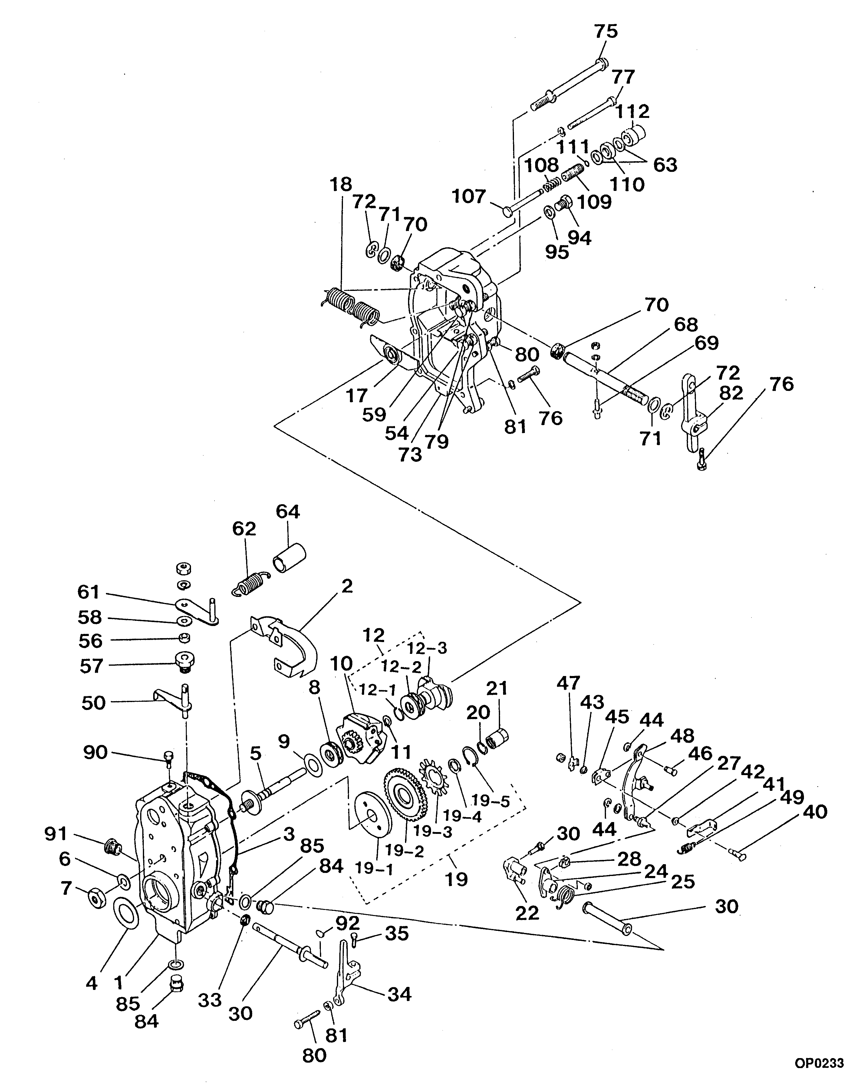
Information governor assy, mec Denso
Scheme #.#:
№
Qty
Part num
Name
Remarks
Manufacture num
000
[01]
09080-09571
GOVERNOR ASSY, MEC
RUV
Include in ##:
09080-09571
as GOVERNOR ASSY, MEC
Cross reference number
Part num
Firm num
Firm
Name
09080-09571
GOVERNOR ASSY, MEC
Information:
Before any service work is to be done on this fuel system, the outer surface of the injection pump housing must be clean.
The fuel injection pump housing and governor has been removed from the engine for illustration purposes. 1. Remove the flange (1) and the flange assembly from the cover.2. Remove the cover (2) from the pump housing. 3. Remove the bypass valve (3) and springs from the pump housing. 4. Install tooling (A) on the fuel injection pump and loosen the bushing from the pump housing. Do not loosen the screws (4) that hold the levers to the shaft when removing or installing pumps. If the levers are moved, fuel pump calibration will be changed. 5. Remove the fuel injection pump (5) from the pump housing. The sleeve (6) on the plunger will slide off the lever as the pump is removed.6. Do Steps 4 and 5 for the remainder of the pumps.Install Fuel Injection Pumps
1. Turn the camshaft until the lifter for the pump to be installed is at its lowest position. 2. Install the fuel injection pump (1) in the bore of the pump housing.3. The sleeve (2) will be engaged with the lever when the pump is installed correctly.
If the levers have been moved on the shaft, fuel pump calibration must be made. (See Testing and Adjusting).
4. Tighten the bushing with tooling (A) to a torque of 70 5 lb.ft. (9.7 0.7 mkg).5. Do Steps 1 through 4 for the remainder of the pumps. 6. Install the bypass valve and spring (3) in the pump housing. 7. Install the cover (5) on the pump housing. Be sure the spring (3) is in the bore in the cover.8. Install the flange (4) and the flange assembly on the cover.Disassemble Fuel Injection Pumps
start by: a) remove fuel injection pumps 1. Remove the bushing (1) and seal from the bonnet (2).2. Remove the ring (3) from the bonnet and barrel (7). Remove the check valve (6) and spring (4) from the bonnet.3. Remove the spring (8) and washer (5). Remove the plunger (9) and sleeve (10). Keep the plunger and sleeve with their respective barrel for installation. Do not use plungers, sleeves and barrels with other plungers, sleeves and barrels.Assemble Fuel Injection Pumps
1. Install the sleeve (4), plunger (5), spring (2) and washer (3) on the barrel (1). Be sure the sleeve and plunger are installed in their original barrel and the large hole in the plunger is up. The sleeve must be installed with the thin flange up.2. Install the check valve and spring in the bonnet. Connect the barrel and bonnet and install the ring. Install the seal and bushing on the bonnet.end by: a) install fuel injection pumps