09080-08590 GOVERNOR ASSY, MEC Denso Cross


Rating:
4
Buy GOVERNOR ASSY, MEC 09080-08590 genuine, new aftermarket engine parts with delivery

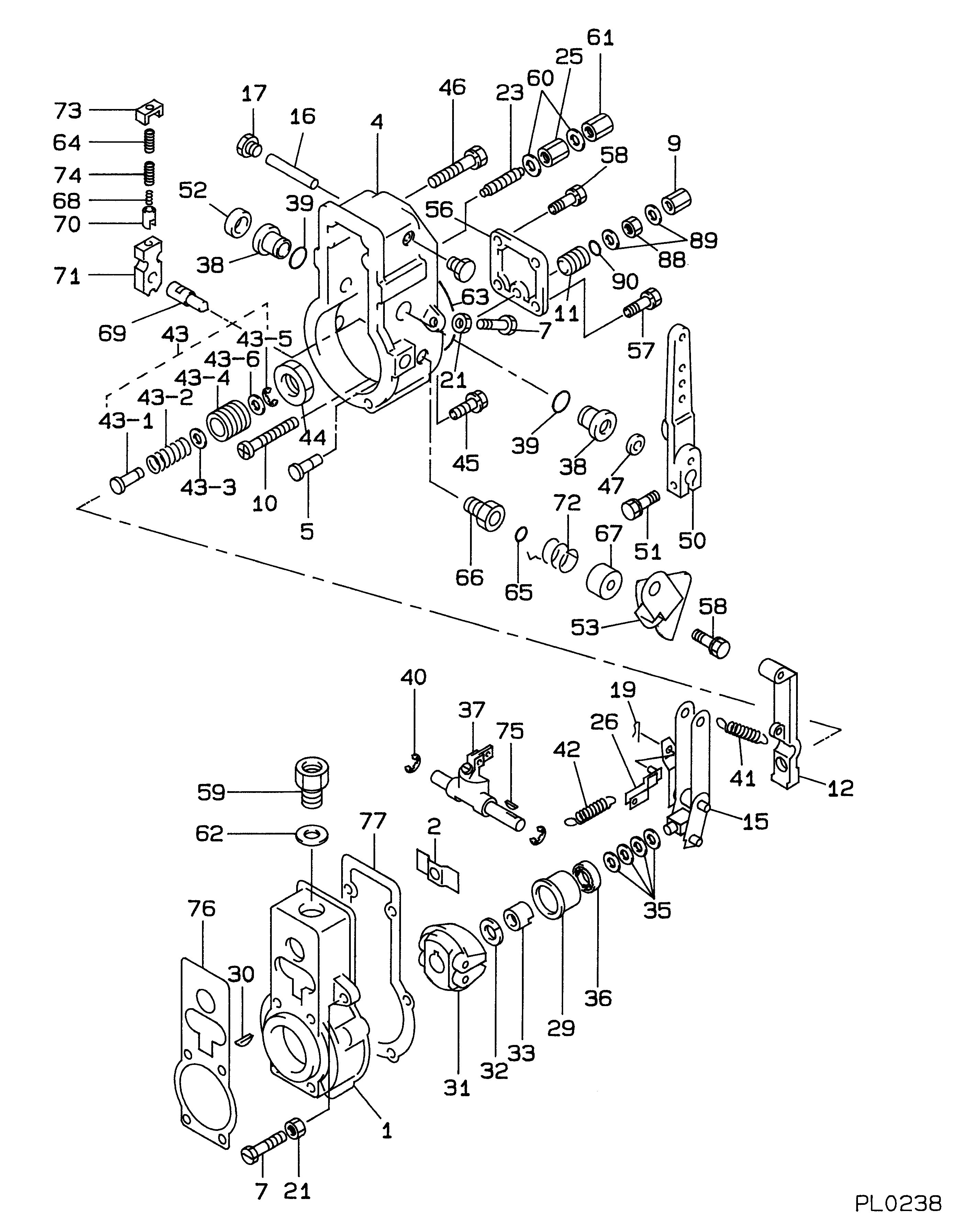
Information governor assy, mec Denso

KIT List:

Part name
Kit1
Kit2
Governor assy, mec
Governor assy, mec

Scheme #.#:

Qty
Part num
Name
Remarks
Manufacture num
000
[01]
09080-08590
GOVERNOR ASSY, MEC
RSV
001
[01]
HOUSING, GOVERNOR
-9311
22301-1230A HINO
001
[01]
HOUSING SUB-ASSY,
9312-
002
[01]
PLATE
22343-1460A HINO
004
[01]
COVER, GOVERNOR
-8611
22302-1220A HINO
004
[01]
COVER, GOVERNOR
8611-
22302-1420A HINO
005
[01]
PIN, STOP
22393-1100A HINO
007
[02]
SCREW, ADJUSTING
M8,L57
22395-1010A HINO
009
[01]
NUT, CAP
22342-1430A HINO
010
[01]
SCREW, STROKE ADJU
22396-1060A HINO
011
[01]
BUSHING
22322-1370A HINO
012
[01]
LEVER, TENSION
22308-1170A HINO
015
[01]
LEVER ASSY, CONTRO
L/R:2
6 056 1325 80 HINO
016
[01]
SHAFT, LEVER SUPPO
22318-1240A HINO
017
[02]
PLUG, SCREW
22845-1210A HINO
019
[01]
PIN, SPLIT
2,L10
22863-1820A HINO
021
[02]
NUT, HEXAGON, W/HO
22825-1080A HINO
023
[01]
CAPSULE, FULL STOP
025
[01]
NUT, ADAPTER LOCK
22825-1400A HINO
026
[01]
SHACKLE ASSY
22317-1140A HINO
029
[01]
SLEEVE, GOVERNOR
22305-1170A HINO
030
[01]
KEY, WOODRUFF
22895-1020A HINO
031
[01]
FLYWEIGHT ASSY
22304-1480A HINO
032
[01]
WASHER, SPRING
T2.5
22877-1220A HINO
033
[01]
NUT, ROUND
22353-1070A HINO
035
[C]
WASHER, PLATE, SK
T0.2
22885-5120A HINO
035
[C]
WASHER, PLATE, SK
T0.3
22885-5130A HINO
035
[C]
WASHER, PLATE, SK
T0.4
22885-5140A HINO
035
[C]
WASHER, PLATE, SK
T0.1
22885-5150A HINO
035
[C]
WASHER, PLATE, SK
T1.0
22885-5160A HINO
036
[01]
BEARING, BALL
22837-1120A HINO
037
[01]
LEVER ASSY, SWIEVE
-9103
22360-1090A HINO
037
[01]
LEVER ASSY, SWIEVE
9103-
038
[02]
BUSHING, LEVER
22322-1360A HINO
039
[02]
O-RING
ID15.8
22817-1060A HINO
040
[02]
WASHER, SNAP
ID15
22887-1050A HINO
041
[01]
SPRING, SPEED CONT
042
[01]
SPRING, START
22331-1280A HINO
043
[01]
ADAPTER ASSY
22404-1710A HINO
043-001
[01]
ADAPTER
6 056 1320 80 HINO
043-002
[01]
SPRING, MECHANICAL
22411-2110A HINO
043-003
[02]
WASHER, PLATE, SK
T0.5
22885-5550A HINO
043-004
[01]
SCREW, ADPTER
22385-2060A HINO
043-005
[01]
E-RING
22863-1810A HINO
043-006
[01]
WASHER
6 056 1308 50 HINO
044
[01]
NUT, ADAPTER LOCK
22825-2090A HINO
045
[04]
BOLT, W/WASHER
M6,L40
22815-1860A HINO
046
[02]
BOLT, W/WASHER
M6,L50
22815-1490A HINO
047
[01]
SEAL, OIL
22827-1370A HINO
050
[01]
LEVER SUB-ASSY, AD
22309-1070A HINO
051
[01]
BOLT, W/WASHER
M6,L22
22815-1230A HINO
052
[01]
CAP, LEVER
22322-1350A HINO
053
[01]
LEVER SUB-ASSY, ST
-8611
22348-2110A HINO
053
[01]
LEVER SUB-ASSY, ST
8611-
22348-2170A HINO
056
[01]
PLATE, COVER
22386-1540A HINO
057
[02]
BOLT, W/WASHER
M6,L14
22815-1430A HINO
058
[03]
BOLT, W/WASHER
M6,L14
22815-1480A HINO
059
[01]
SCREW,PLUG
22845-1110A HINO
060
[02]
WASHER, AIR BLEEDE
22847-2150A HINO
061
[01]
NUT, CAP
22825-2060A HINO
062
[01]
WASHER, COPPER PLA
T1.5
96542-2150A HINO
063
[01]
PACKING, RUBBER PL
22817-1070A HINO
064
[01]
SPRING, B
22341-1610A HINO
065
[01]
O-RING
22817-1440A HINO
066
[01]
BUSHING, BEARING
22322-1180A HINO
067
[01]
COVER, SPRING
22351-1650A HINO
068
[01]
SPRING, B
22341-1620A HINO
069
[01]
SHAFT, MECHANICAL
22349-1120A HINO
070
[01]
CUP, SPRING
22358-1490A HINO
071
[01]
LEVER, SUPPORT
22349-1270A HINO
072
[01]
SPRING, RETURN
22341-2500A HINO
073
[01]
PLATE, CAP
22351-1330A HINO
074
[01]
SPRING, B
22351-1320A HINO
075
[01]
KEY, WOODRUFF
22891-1060A HINO
076
[01]
GASKET
-9408
22847-1570A HINO
076
[01]
GASKET
9409-
077
[01]
GASKET
-9309
22847-1200A HINO
077
[01]
GASKET
9310-
088
[01]
NUT, HEXAGON
M8
22825-1100A HINO
089
[02]
WASHER, COPPER PLA
T1
22867-1500A HINO
090
[01]
O-RING
ID12.3
22817-1080A HINO

Include in ##:

09080-08590 as GOVERNOR ASSY, MEC

Cross reference number


Part num
Firm num
Firm
Name
09080-08590 
 
GOVERNOR ASSY, MEC


Information:


To prevent dust from entering the fuel system, cover all openings in the injection pump, nozzle inlet connectors and injection pipes.
Removal of Fuel Injection Pump
Removal of fuel injection pump (1)
Removal of fuel injection pump (2)(1) Check the alignment marks stamped on the flange of the fuel injection pump and the pump mounting flange.(2) Remove the front cover from the engine.(3) Place alignment marked on the fuel injection pump gear and idler gear.(4) Unscrew the mounting bolts from the fuel injection pump flange, and remove the fuel injection pump together with the flange from the front plate. (a) After the fuel injection pump is removed, do not turn the engine.(b) When removing the pump gear, loosen the gear retaining nut while the pump is mounted on the engine.Disassembly, Inspection and Reassembly of Fuel System
Disassembly of Fuel Injection Nozzles
Inspection of Fuel Injection Nozzles
Inspection of fuel injection nozzle valve openingCheck each fuel injection nozzle for the following, and if defects are found, repair or replace the fuel injection nozzle.(1) Inspection of injection start pressure(a) Install each fuel injection nozzle on the nozzle tester, and move the handle up and down to release air.(b) Operate the handle of the tester at a rate of about 1 stroke per second, and read the indication on the pressure gage. The indication rises slowly, and the indicator oscillates during spraying. To obtain the injection start pressure value, read the indication when the indicator starts to oscillate.(c) If the injection start pressure deviates significantly from the standard value, disassemble the fuel injection nozzle, and make an adjustment by changing the washer thickness.
Replacement of fuel injection nozzle tip 0.1 mm [0.0039 in.] thickness of shims will change the injection pressure 0.98 Mpa (10 kgf/cm2 [142 psi]. The shims are available in 10 different thickness from 1.25 to 1.70 mm [0.0492 to 0.0669 in.] increment of 0.05 mm [0.0020 in.]
Never tap the tip of the nozzle tip when removing the nozzle tip.
(2) Inspection f fuel injection nozzle spray pattern
Inspection of spray pattern of fuel injection nozzle(a) When inspecting each fuel injection nozzle with the nozzle tester, also check the nozzle for clogs, spray pattern and leakage.(b) Make sure that the fuel is sprayed straight from the nozzle when the handle of the tester is operated at a rate of about 1 stroke per second.(3) Cleaning and replacement of faulty nozzles
Cleaning of fuel injection nozzle tip(a) Loosen the nozzle retaining nut, remove the nozzle tip, and clean the needle valve and body.
Never tap the tip of the nozzle tip when removing the nozzle tip.
(b) Use a fresh cleaning solution to clean the needle valve and body. after cleaning, assemble the needle valve and body in clean diesel fuel. The needle valve and body are precision finished. Handle them carefully, and do not change the combination of parts.(c) Tighten the nozzle retaining nut on the nozzle tip to the specified torque.(d) If the spray pattern is still not acceptable after adjustment and cleaning, replace the nozzle tip. (a) Never touch

Have questions with 09080-08590?


Group cross 09080-08590

Back to top