Rating:
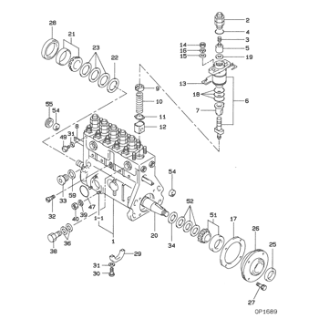
Information element sub-assy, Denso
Include in ##:
09010-08382
as ELEMENT SUB-ASSY,
Cross reference number
Part num
Firm num
Firm
Name
09015-05881
ELEMENT SUB-ASSY,
Information:
1. Remove oil line (1), fuel line (2), fuel ratio control line (3). 2. Remove clip (4) and use tool (A) to slide sleeve (5) into the cylinder head. 2. With tooling (B) in place, remove clip and pin (6).3. Remove three bolts (7). Remove the governor with the o-ring seal. Care must be taken not to damage the fuel control linkage. Install in reverse order. After installation, check the Fuel Setting Adjustment. Refer to Systems Operation Testing And Adjusting section of this service manual.Disassemble And Assemble Fuel Transfer Pump
Start By:a. remove governor and fuel transfer pump 1. Install governor on governor repair stand (A).
There is spring force behind cover (1). Hold cover (1) in position, and slowly remove bolts (2), to release the spring force.
2. Remove three bolts (2) and cover (1).3. Remove fitting (3) and check valve (4) from cover (1). Inspect parts for wear.4. Remove spring (5), piston (6) and inspect for wear. Replace the spring and the complete piston assembly if necessary.5. Remove upper o-ring (7).6. Remove sleeve assembly (8). Inspect tappet face (9) for wear. Replace complete assembly if necessary. Inspect cam surface, if damaged, replace the front housing assembly.7. Remove lower o-ring seal (10).8. Remove fitting (11) and check valve (12). Inspect for wear. The following steps are for the assembly of the fuel transfer pump.9. Lightly lubricate fitting (11) and the check valve bore with engine oil. Install the check valve with the sealing face down. With the o-ring in place, install fitting (11).10. Lubricate the sleeve bore. Install lower o-ring seal (10). Apply 8T2998 Camshaft Lubricant to tappet face (9). Slide sleeve assembly (8) into place, aligning the flat on the sleeve with the flat on the housing bore. Install upper o-ring (7).11. Lightly lubricate piston assembly (6) with engine oil. Install piston assembly (6) and spring (5).12. Lightly lubricate fitting (3) and the check valve bore with engine oil. Install the check valve with the sealing face toward the fitting. With the o-ring in place, install fitting (3).13. Position cover (1) compressing spring (4), and install bolts (2).14. Remove governor from tool (A).End By:a. install governor and fuel transfer pumpRemove And Install Fuel Ratio Control
Start By:a. remove the governor The fuel ratio control must be adjusted using the governor calibration bench. It can not be adjusted while it is on the engine.1. Disconnect fuel ratio control line (1). Remove bolt (2) and clamp (3). 2. Remove fuel ratio control assembly (4) by working stem (5) out of fork (6). The following steps are for the installation of the fuel ratio control.
When removing plug (7), care must be taken to avoid damaging the internal parts of the governor.
3. Remove housing plug (7), using the blade of a screwdriver, accessed thru the fuel ratio control assembly location in the governor housing. This exposes adjustment screw (8).4. Install the fuel ratio control assembly, insuring that stem (5) is engaged thru fork (6). [Reach thru the other side to help engage fork
