Rating:
Information bolt, hexagon Denso
Include in ##:
Number on scheme 112

09600-01771
as BOLT, HEXAGON
Cross reference number
Part num
Firm num
Firm
Name
91107-05351
BOLT, HEXAGON
Information:
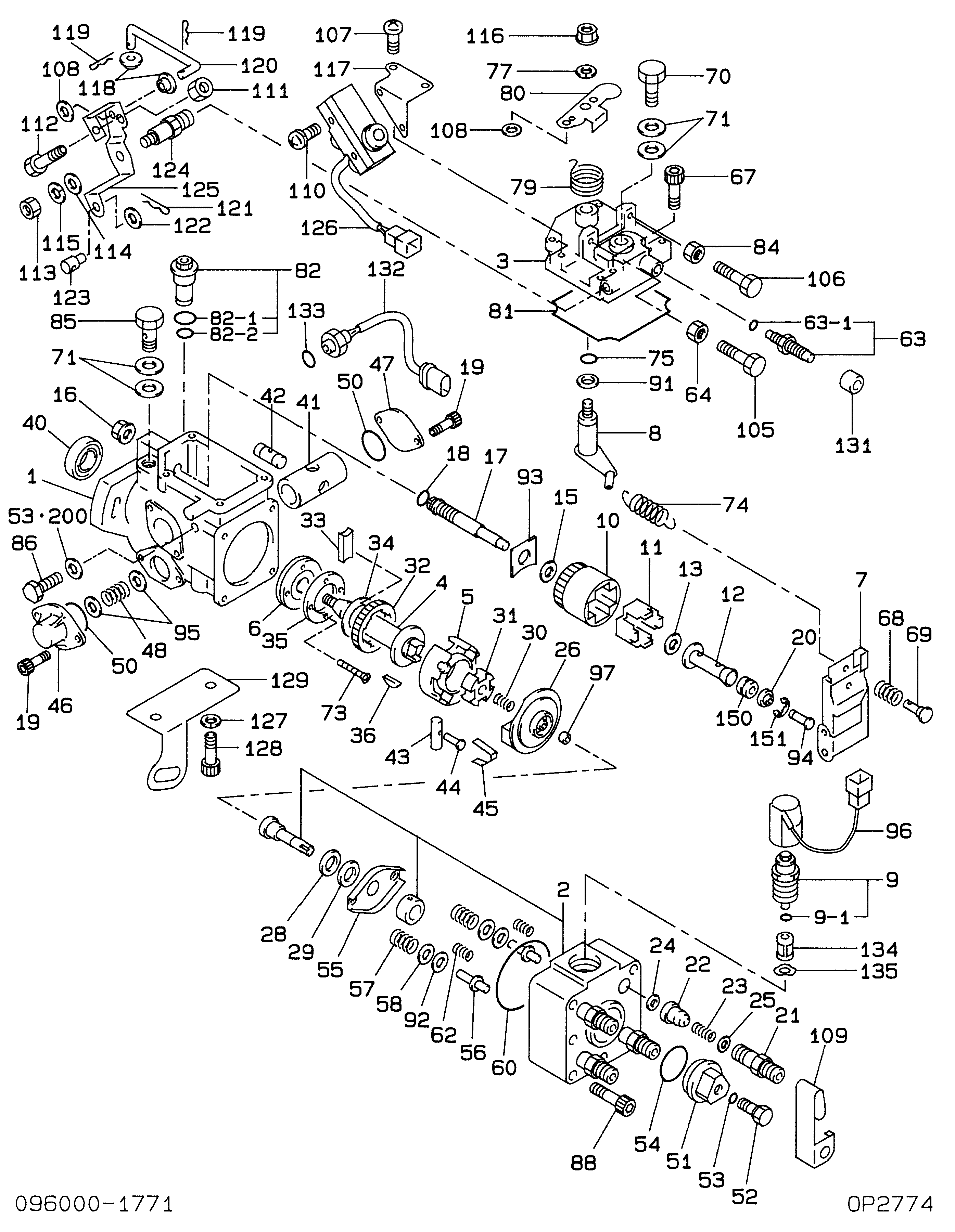
1. Remove three bolts (1). Remove cover (2) and gasket from the timing advance housing. Remove two bolts (4) and clamps. Remove nut (3), disconnect the wiring harness and remove timing solenoid (5). 2. Disconnect wiring harness (7). Use tool (A) to loosen locknut (9). Remove collar (10) and bracket (8). Remove timing position sensor (6) and spring from the timing advance housing. 3. Rotate the bellcrank away from the timing advance unit and pin the bellcrank in place using a #2 phillips screwdriver. Remove seven nuts (12) and remove housing (11) and gasket. The screwdriver must be inserted between the large and small leg of the bellcrank. 4. Remove two bolts (13). Remove bellcrank assembly (14) (with bellcrank pinned) and gasket. 5. Remove the screwdriver from bellcrank assembly (14). 6. Remove retaining ring (15). Remove bellcrank (17) and spring (16). 7. Remove four bolts (18) and timing advance unit (19). 8. Remove gear (20) from the fuel injection pump cam assembly.Install Timing Advance Unit
Part of the Pump And Governor Reconditioning Tool Group And the 6V4096 Governor Adjustment Tool Group. 1. Install gear (20) on the fuel injection pump shaft. 2. Install two 3/8 NC guide pins (21) into the fuel injection pump shaft.3. Lubricate the rubber seal on the fuel injection pump and governor drive hub with engine oil. Install fuel injection pump and governor drive (19) over guide pins (21) on the fuel injection pump shaft. Apply pressure on plate (22) when installing fuel injection pump and governor drive. 4. Install four bolts (18) hand tight. Tighten two of bolts (18) to a torque of 3 N m (27 lb.in.). 5. Put the No. 1 piston at top center on the compression stroke. Make reference to Finding Top Center Compression Position for No. 1 Piston in Testing And Adjusting (Service Manual Form No. SEBR0544). Remove the timing bolt from the flywheel, and use tool (E) to rotate the crankshaft clockwise (opposite direction of normal engine rotation) 45°. 6. Remove plug (23) from the fuel injection pump housing. 7. Install tool (F) in the fuel injection pump housing as shown. Slowly rotate the crankshaft counterclockwise (direction of engine rotation) until the timing pin goes into the slot in the fuel injection pump camshaft.
Too much pressure on the timing pin can damage the fuel injection pump or the timing pin.
8. Put the timing bolt in the timing hole in the flywheel housing. Rotate the crankshaft counterclockwise (as seen from the flywheel end of the engine) until the fuel pump camshaft is tight against timing pin (F). This removes gear clearance from the drive train. If the bolt can be installed in the timing hole in the flywheel, the timing of the fuel injection pump is correct.9. If the timing bolt does not go into the timing hole in the flywheel, the timing is not correct. Do the steps that follow to adjust the fuel injection pump timing.a. Loosen four bolts (18). With tool (F) installed and the