09010-06431 BODY ASSY, INJECTI Denso Cross


Rating:
46
Buy BODY ASSY, INJECTI 09010-06431 genuine, new aftermarket engine parts with delivery

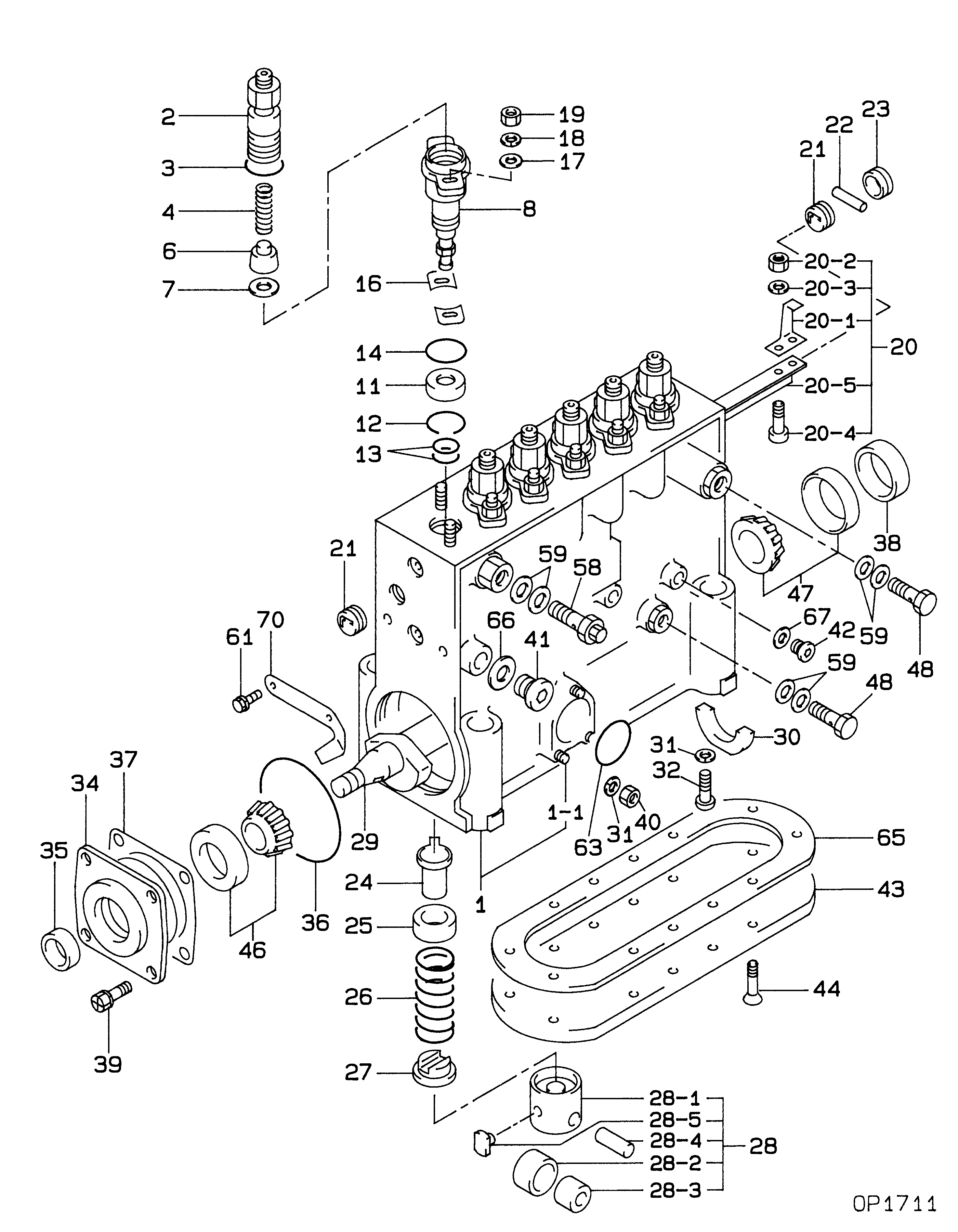
Information body assy, injecti Denso

Scheme #.#:

Qty
Part num
Name
Remarks
Manufacture num
000
[01]
09010-06431
BODY ASSY, INJECTI
NE6
001
[01]
HOUSING SUB-ASSY,
001-001
[03]
BOLT, STUD
M6,L26
002
[06]
HOLDER SUB-ASSY, D
003
[06]
O-RING
004
[06]
SPRING, DELIVERY V
006
[06]
VALVE SUB-ASSY, IN
MK:1750
007
[06]
GASKET, DELIVERY V
008
[06]
ELEMENT SUB-ASSY,
MK:3730
011
[06]
COVER, ELEMENT
-8712
011
[06]
COVER, ELEMENT
8712--9005
011
[06]
COVER, ELEMENT
9005-
012
[06]
RING, SNAP
ID18.2
013
[12]
O-RING
ID15.0 -8806
013
[12]
O-RING
ID15 8806-
014
[06]
O-RING
-9103
014
[06]
O-RING
ID28.8 9104-
016
[C]
SHIM, ELEMENT HOLD
T1.4
016
[C]
SHIM, ELEMENT HOLD
T1.45
016
[C]
SHIM, ELEMENT HOLD
T1.5
016
[C]
SHIM, ELEMENT HOLD
T1.55
016
[C]
SHIM, ELEMENT HOLD
T1.6
016
[C]
SHIM, ELEMENT HOLD
T0.7
016
[C]
SHIM, ELEMENT HOLD
T0.75
016
[C]
SHIM, ELEMENT HOLD
T0.8
016
[C]
SHIM, ELEMENT HOLD
T0.85
016
[C]
SHIM, ELEMENT HOLD
T0.9
016
[C]
SHIM, ELEMENT HOLD
T0.95
016
[C]
SHIM, ELEMENT HOLD
T1.0
016
[C]
SHIM, ELEMENT HOLD
T1.05
016
[C]
SHIM, ELEMENT HOLD
T1.1
016
[C]
SHIM, ELEMENT HOLD
T1.15
016
[C]
SHIM, ELEMENT HOLD
T1.2
016
[C]
SHIM, ELEMENT HOLD
T1.25
016
[C]
SHIM, ELEMENT HOLD
T1.3
016
[C]
SHIM, ELEMENT HOLD
T1.35
017
[12]
WASHER, STEEL PLAT
018
[12]
WASHER, SPRING
M10
019
[12]
NUT, HEXAGON
M10,L8
020
[01]
RACK ASSY, CONTROL
020-001
[01]
ARM
020-002
[01]
NUT, HEXAGON
M5
020-003
[01]
WASHER, SPRING
M5
020-004
[01]
SCREW, CROSSRECESS
M5,L12
020-005
[01]
RACK, CONTROL
021
[02]
BUSHING, CONTROL R
022
[01]
PIN, STRAIGHT
023
[01]
BUSHING, CONTROL R
024
[06]
SLEEVE SUB-ASSY, C
-8903
024
[06]
SLEEVE SUB-ASSY, C
8904-
025
[06]
SEAT, SPRING, UPR
026
[06]
SPRING, PUMP PLUNG
027
[06]
SEAT, SPRING, LWR
028
[06]
TAPPET SUB-ASSY,IN
028-001
[06]
BODY, INJECTION PU
-9303
028-001
[06]
TAPPET, INJECTION
9303-
028-002
[06]
ROLLER, INJECTION
-9211
028-002
[06]
ROLLER, INJECTION
9211-
028-003
[06]
BUSHING, INJECTION
028-004
[06]
PIN, INJECTION PUM
028-005
[06]
SLIDER
9303-
029
[01]
CAMSHAFT, INJECTIO
030
[01]
BEARING, CENTER
031
[09]
WASHER, SPRING
FOR M6 -9611
031
[05]
WASHER, SPRING
FOR M6 9611-
032
[02]
SCREW, SLOTTED OVA
M6,L18 -9408
032
[02]
SCREW
M6,L18 9408-
034
[01]
COVER, BEARING
035
[01]
SEAL, OIL
036
[01]
O-RING
ID63.5
037
[2C]
PLATE, SHIM
T0.03
037
[2C]
PLATE, SHIM
T0.05
037
[2C]
PLATE, SHIM
T0.07
037
[2C]
PLATE, SHIM
T0.1
037
[2C]
PLATE, SHIM
T0.2
037
[2C]
PLATE, SHIM
T0.3
037
[2C]
PLATE, SHIM
T0.5
038
[01]
RETAINER, BEARING
039
[04]
BOLT, W/WASHER
M8,L20
040
[03]
NUT, HEXAGON
M6
041
[01]
PLUG, SCREW
042
[06]
PLUG, SCREW
043
[01]
PLATE, INJECTION P
044
[12]
SCREW, SLOTTED POL
M6,L12
046
[01]
BEARING, ROLLER
047
[01]
BEARING, ROLLER
OD52,ID25
048
[02]
SCREW, HOLLOW
M14,L10
058
[01]
VALVE ASSY, OVERFL
2.6K
059
[06]
WASHER, FUEL PIPE
061
[02]
BOLT, W/WASHER
M6,L14
063
[01]
GASKET, FEED PUMP
-8912
063
[01]
O-RING
ID32.0 8912-
065
[01]
GASKET, INJECTION
066
[01]
WASHER, COPPER PLA
T2
067
[06]
WASHER, COPPER PLA
T1
070
[01]
NEEDLE, TIMING

Cross reference number


Part num
Firm num
Firm
Name
09010-06431 
 
BODY ASSY, INJECTI


Information:


TIMING PIN HOLE PLUG (Typical Example)
1. Plug.2. Rotate the crankshaft CLOCKWISE (as viewed from front of engine) until the timing pin drops into the timing slot in the fuel injection pump camshaft.3. Disconnect wire (2) from fuel shut off solenoid.4. Remove the tachometer drive adapter housing (3).
WIRE AND HOUSING (Typical Example)
2. Wire. 3. Tachometer drive adapter housing.5. Use ratchet (4) and socket (5) to remove the tachometer drive adapter shaft.
REMOVING SHAFT
4. 8H8572 Ratchet. 5. 9S5031 Deep Well Socket.6. Using puller group (6), thread the 9S8528 Bolt Assembly into the camshaft. Do not force the bolt assembly. It should thread easily. Install the 9S8527 Bolt by threading it into the gear carrier or adapter. Then tighten the 9S8527 Bolt with a wrench until the gear carrier or adapter "pops" loose. Remove the 9S8520 Puller Group.
LOOSENING CAMSHAFT DRIVE GEAR
6. 9S8520 Puller Group.7. Remove the plug from the timing hole (8) in the front cover and insert bolt (7). The cover retaining bolt from hole (9) may be used.8. Rotate crankshaft CLOCKWISE (as viewed from front of engine) until bolt (7) threads into the timing gear and is centered in timing hole (8). With timing pin in slot in fuel pump camshaft and the bolt (7) through the front cover and threaded into the timing gear, the fuel injection pump camshaft is timed to the engine.
INSTALLING BOLT
7. 1D4539 Bolt [5/16 in. - 18 NC, 2.5 in. (63.5 mm) long]. 8. Timing hole. 9. Hole.9. Remove the fuel injection pump housing retaining bolts (10).
RETAINING BOLTS (Typical Example)
10. Retaining bolts (three).
REMOVING HOUSING (Typical Example)10. Attach a hoist and remove the fuel injection pump housing and governor as a unit, the weight is approx. 55 lbs. (23 kg).Install Fuel Injection Pump Housing and Governor
1. Attach a hoist and install the fuel injection pump housing and governor as a unit. Install the fuel injection pump housing retaining bolts.2. Install the tachometer drive adapter shaft and tighten shaft retaining nut to 32 2 lb. ft. (4.4 0.3 mkg).3. To check timing remove the timing pin and the bolt. Rotate the crankshaft two revolutions CLOCKWISE (as viewed from front of engine) and install the timing pin and bolt back in place. If the timing pin or bolt can not be installed, the fuel injection pump camshaft must be retimed.4. Remove the bolt (7) from the timing gear and install in hole (9). Install the plug into timing hole (8).5. Remove the timing pin from the timing slot in the fuel injection pump camshaft and install the plug in the timing hole.6. Install the tachometer drive adapter housing. Connect the wire to the fuel shut off solenoid.

Have questions with 09010-06431?


Group cross 09010-06431

Back to top