09010-06020 BODY ASSY, INJECTI Denso Cross


Rating:
60
Buy BODY ASSY, INJECTI 09010-06020 genuine, new aftermarket engine parts with delivery

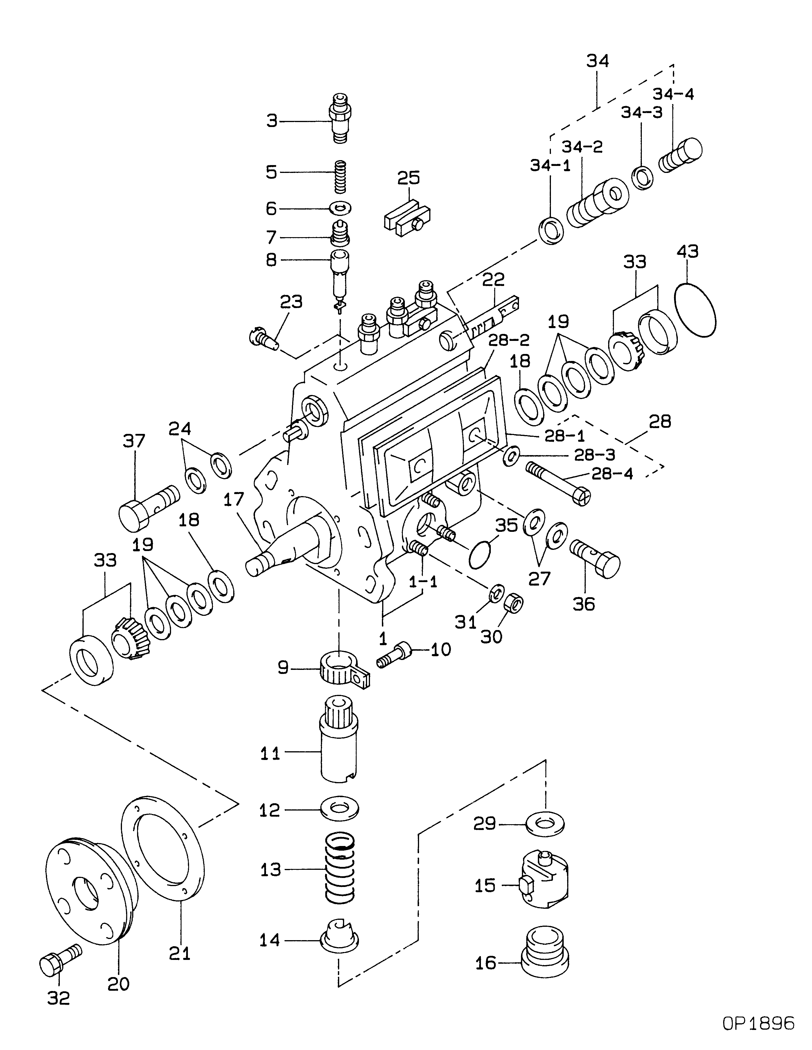
Information body assy, injecti Denso

Scheme #.#:

Qty
Part num
Name
Remarks
Manufacture num
000
[01]
BODY ASSY, INJECTI
A4:DRIV.16.8
001
[01]
HOUSING KIT, INJEC
001-001
[03]
BOLT, STUD
M6,L26
003
[04]
HOLDER, DELIVERY V
005
[04]
SPRING, DELIVERY V
006
[04]
GASKET, DELIVERY V
D18,ID12
007
[04]
VALVE SUB-ASSY, IN
MK:161S5
008
[04]
ELEMENT SUB-ASSY,
MK:185-6
009
[04]
PINION, PLUNGER CO
010
[04]
SCREW, PLUNGER CON
011
[04]
SLEEVE, PLUNGER CO
012
[04]
SEAT, SPRING, UPR
013
[04]
SPRING, PUMP PLUNG
L49.4
014
[04]
SEAT, SPRING, LWR
015
[04]
TAPPET SUB-ASSY,IN
016
[04]
PLUG, INJECTION PU
M26,D30
017
[01]
CAMSHAFT, INJECTIO
D16.8
018
[02]
RING, CAMSHAFT ADJ
019
[6C]
PLATE, CAMSHAFT SH
T0.1
019
[6C]
PLATE, CAMSHAFT SH
T0.12
019
[6C]
PLATE, CAMSHAFT SH
T0.14
019
[6C]
PLATE, CAMSHAFT SH
T0.16
019
[6C]
PLATE, CAMSHAFT SH
T0.18
019
[6C]
PLATE, CAMSHAFT SH
T0.5
019
[6C]
PLATE, CAMSHAFT SH
T0.3
019
[6C]
PLATE, CAMSHAFT SH
T1.0
019
[6C]
PLATE, CAMSHAFT SH
T1.5
019
[6C]
PLATE, CAMSHAFT SH
T2.0
020
[01]
COVER, BEARING
021
[01]
GASKET, BEARING CO
022
[01]
RACK, CONTROL
023
[01]
SCREW, RACK GUIDE
M6,L9.8
024
[02]
WASHER, FUEL PIPE
ID13.8
025
[02]
PLATE SET, VALVE H
IRON
027
[02]
WASHER, INJECTION
T1,D13.9
028
[01]
COVER SUB-ASSY, IN
-9511
028
[01]
COVER SUB-ASSY, IN
9512-
028-001
[01]
PROCESSING DRAWING
028-002
[01]
GASKET, INJECTION
028-003
[02]
PACKING, AIR BLEED
ID6.7
028-004
[02]
SCREW
M6,L54
029
[4C]
PLATE, TAPPET ADJU
T0.6
029
[4C]
PLATE, TAPPET ADJU
T0.7
029
[4C]
PLATE, TAPPET ADJU
T0.8
029
[4C]
PLATE, TAPPET ADJU
T0.9
029
[4C]
PLATE, TAPPET ADJU
T1.0
029
[4C]
PLATE, TAPPET ADJU
T1.1
029
[4C]
PLATE, TAPPET ADJU
T1.2
029
[4C]
PLATE, TAPPET ADJU
T1.3
029
[4C]
PLATE, TAPPET ADJU
T1.4
029
[4C]
PLATE, TAPPET ADJU
T0.1
029
[4C]
PLATE, TAPPET ADJU
T0.2
029
[4C]
PLATE, TAPPET ADJU
T0.3
029
[4C]
PLATE, TAPPET ADJU
T0.4
029
[4C]
PLATE, TAPPET ADJU
T0.5
029
[4C]
PLATE, TAPPET ADJU
T0.15
029
[4C]
PLATE, TAPPET ADJU
T0.13
030
[03]
NUT, HEXAGON
M6,L5
031
[03]
WASHER, SPRING
T1.5
032
[04]
BOLT, W/WASHER
M6,L14
033
[02]
BEARING, ROLLER
D40,T13
034
[01]
BLEEDER SUB-ASSY,
034-001
[01]
WASHER, AIR BLEEDE
T1.6ID12
034-002
[01]
NIPPLE, AIR BLEEDE
034-003
[01]
PACKING, AIR BLEED
ID6.7
034-004
[01]
SCREW, AIR BLEEDER
035
[01]
O-RING
ID32.0
036
[01]
SCREW, HOLLOW
M10,L19
037
[01]
SCREW, HOLLOW
M14,L26
043
[01]
O-RING
ID45.5

Cross reference number


Part num
Firm num
Firm
Name
09010-06020 
 
BODY ASSY, INJECTI


Information:


Illustration 1 g00596626
(1) Potentiometer (2) Light Emitting Diode (3) The Normally Closed Contact (4) Common Contact (5) Normally Open Contact
Preset the variable voltage power supply to 22 VDC.
Secure the variable voltage power supply.
Use the 4P-4029 Adjustment Tool to turn the potentiometer for the low voltage alarm module counterclockwise. Turn the potentiometer 25 times.
Remove the wire from the low voltage alarm module's positive terminal. Remove the wire from the low voltage alarm module's negative terminal.
Connect the power supply's positive lead to the low voltage alarm module's positive terminal.
Connect the power supply's negative lead to the low voltage alarm module's negative terminal.
Connect the multimeter to the N.O. contact and connect the multimeter to the COM contact. Set the multimeter to the function for measuring ohms. The multimeter should read "OL".
Energize the power supply.
Verify that the voltage is 22 VDC.
If the voltage is not 22 VDC, adjust the power supply.
Slowly turn the potentiometer for the low voltage alarm module clockwise until the LED illuminates.Note: The relay will energize after the LED illuminates. This occurs in 50 15 seconds.
Observe the multimeter in order to verify that the relay energized. The resistance reading should be low when the relay is energized.
Increase the output of the power supply to 24 VDC.Note: The LED and the relay de-energize simultaneously.
Remove the power supply's negative lead from the low voltage alarm module.
Remove the power supply's positive lead from the low voltage alarm module.
Remove the multimeter's leads from the low voltage alarm module.
Connect the system's wire to the low voltage alarm module's positive terminal. Connect the system's wire to the low voltage alarm module's negative terminal.

Have questions with 09010-06020?


Group cross 09010-06020

Back to top