Rating:
Information bearing, ball Denso
Compare Prices: .
As an associate, we earn commssions on qualifying purchases through the links below

949100-0080 Qty 4: Sealed Ball Bearing (Econ Version) Fits Denso
Generic Package included: 1x 949100-0080 Qty 4: Sealed Ball Bearing (Econ Version) Fits Denso as the picture . || High-Performance Efficiency: gineered for maximum efficiency, this product delivers exceptional performance without compromising on quality. It’s a versatile replacement suitable for various applications. || Identify the model: USE Ctrl + F to SEARCH your model number inside the Product Description. || Note: If you are not sure about the compatibility please contact us for advice. we will solve your problem within 24 hours || Note: If you are not sure about the compatibility please contact us for advice. we will solve your problem within 24 hours
Generic Package included: 1x 949100-0080 Qty 4: Sealed Ball Bearing (Econ Version) Fits Denso as the picture . || High-Performance Efficiency: gineered for maximum efficiency, this product delivers exceptional performance without compromising on quality. It’s a versatile replacement suitable for various applications. || Identify the model: USE Ctrl + F to SEARCH your model number inside the Product Description. || Note: If you are not sure about the compatibility please contact us for advice. we will solve your problem within 24 hours || Note: If you are not sure about the compatibility please contact us for advice. we will solve your problem within 24 hours

949100-0080 Qty 30: Sealed Ball Bearing (Econ Version) Fits Denso
Reliable Aftermarket Parts OEM Numbers Are Provided for Reference Only. Please Verify Fit Prior To Ordering. || Please Note: Some Listings Use Stock Images for Reference and May Differ from the Actual Product. || This Aftermarket Part Is Made to Meet or Exceed Manufacturer (OEM) Specifications. || All OEM part numbers and logos are to be used for identification purposes only.
Reliable Aftermarket Parts OEM Numbers Are Provided for Reference Only. Please Verify Fit Prior To Ordering. || Please Note: Some Listings Use Stock Images for Reference and May Differ from the Actual Product. || This Aftermarket Part Is Made to Meet or Exceed Manufacturer (OEM) Specifications. || All OEM part numbers and logos are to be used for identification purposes only.

949100-0080 Qty 50: Sealed Ball Bearing (Econ Version) Fits Denso
Reliable Aftermarket Parts OEM Numbers Are Provided for Reference Only. Please Verify Fit Prior To Ordering. || Please Note: Some Listings Use Stock Images for Reference and May Differ from the Actual Product. || This Aftermarket Part Is Made to Meet or Exceed Manufacturer (OEM) Specifications. || All OEM part numbers and logos are to be used for identification purposes only.
Reliable Aftermarket Parts OEM Numbers Are Provided for Reference Only. Please Verify Fit Prior To Ordering. || Please Note: Some Listings Use Stock Images for Reference and May Differ from the Actual Product. || This Aftermarket Part Is Made to Meet or Exceed Manufacturer (OEM) Specifications. || All OEM part numbers and logos are to be used for identification purposes only.
Include in ##:
Number on scheme 045

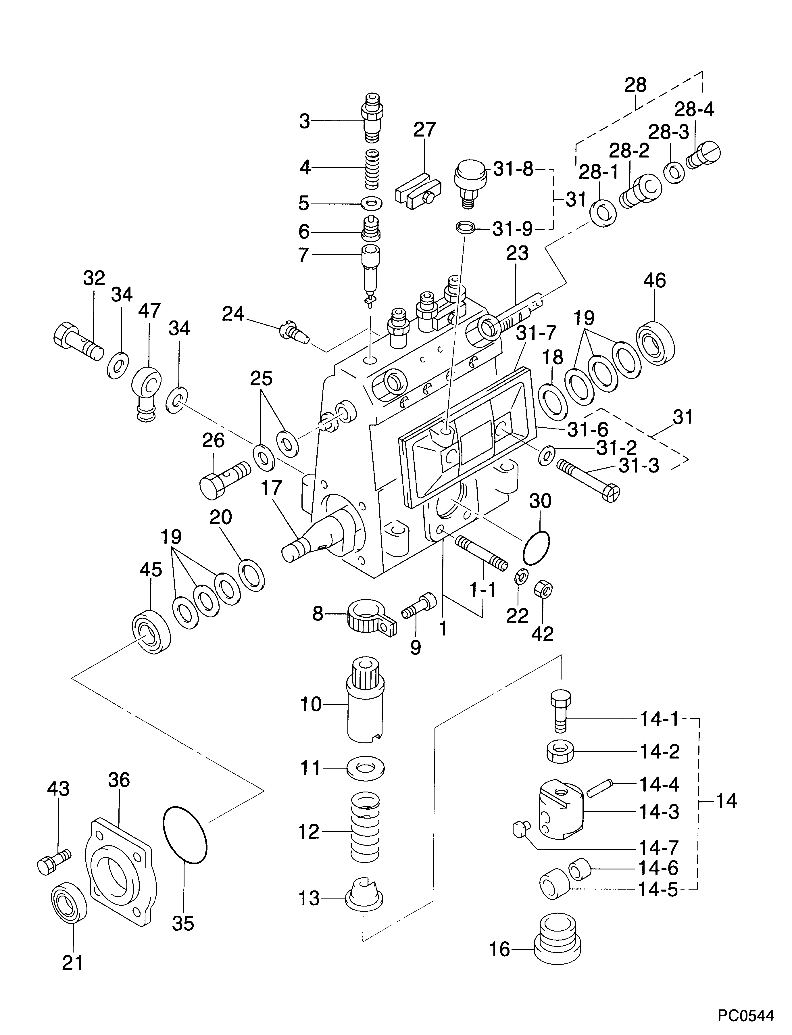
09010-00111
as BEARING, BALL
Cross reference number
Part num
Firm num
Firm
Name
94910-00080
BEARING, BALL
Information:
Troubleshooting
For complete coverage of troubleshooting, see the Troubleshooting Section of Service Manual, Challenger 75 Ag Tractor, Form No. SENR4960.Engine Vibration Troubleshooting
The troubleshooting chart provides a definite sequence to be followed for a logical procedure to determine the frequency and amplitude of vibration so that the source of the vibration can be located and corrected.1. The customer must be asked questions to determine whether his complaint is valid, or whether his diagnosis of the actual problem is correct.Some of the questions that must be asked are as follows:a. What components are vibrating?b. In what speed range does this vibration become excessive?c. Does clutch operation affect the vibration?d. What is the history of the problem?2. Run the engine through the idle speed range and note all vibrating components. Look for any loose or broken mounts, brackets, and fasteners. Repair and tighten any fixtures.3. Check idle speed range with clutch disengaged. If vibrations subside, there is a balance problem with the clutch disc. The clutch disc must be repaired or replaced.4. Further analysis requires the use of a vibration instrument. Any instrument which can accurately measure the displacement of the vibration (usually in mils-inch/1000) and the frequency (cycles per second) will be sufficient. The 4C3030 Vibration Analyzer Group can be used to provide a quick and complete identification of all vibration frequencies present in a constant speed measurement. Make reference to Operation Manual, Form No. NEHS0525 for additional information for troubleshooting vibration complaints with the 4C3030 Vibration Analyzer Group. The following steps assume the use of a vibration instrument such as the IRD Mechanalysis Model 320 or an equivalent instrument can be used to analyze vibration. Make reference to Special Instruction, Troubleshooting Engine Vibration In Vehicular Equipment, Form No. SEHS7914 for additional information for troubleshooting vibration complaints.5. Measure vibration of cab components which have the objectionable vibration.Run engine slowly through the speed range and measure vibration with the instrument filter OUT. When peak amplitudes are found, run the engine at the speeds they occur and with the instrument filter IN, find the frequency of the vibration.If the frequency of vibration is 1/2 times of engine rpm (1/2 order), the vibration is caused by a cylinder misfiring. This must be corrected before further vibration analysis is made.If the frequency of vibration is 3 times engine rpm (3rd order), no corrective action can be taken on the engine because this is the firing frequency of the 3176 Engine. The problem is in the cab or chassis resonance.If frequency is some order other than 1/2 or 3rd order vibrations, then further measurements must be made on the engine.6. Measurements taken on the engine must be made perpendicular to the crankshaft at the front and rear of the engine in vertical and horizontal directions.7. Record all vibrations over 4.0 mils and the engine rpm at which it occurs (100 rpm intervals are sufficient) with instrument filter OUT. Note any sudden increase and decrease in amplitudes. These occur in resonant speed ranges.If no amplitudes exceed 4.0