Rating:
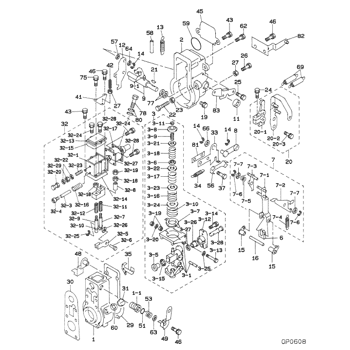
Information arm sub-assy Denso
Include in ##:
09130-03331
as ARM SUB-ASSY
Cross reference number
Part num
Firm num
Firm
Name
09115-90640
ARM SUB-ASSY
0911590640
22343-4180A
HINO
ARM SUB-ASSY
0911590640
ME743020
MITSUBISHI
ARM SUB-ASSY
Information:
Introduction
If the engine turns over but the engine does not start, refer to Operation and Maintenance Manual, "Fuel System - Prime" and Troubleshooting, "Engine Cranks but Will Not Start".If the engine will not start, new service parts are available.The new service parts are the following components.
257-2382 Plug
257-2381 Pin
258-8149 Spring Removal Procedure
Contact with high pressure fuel may cause fluid penetration and burn hazards. High pressure fuel spray may cause a fire hazard. Failure to follow these inspection, maintenance and service instructions may cause personal injury or death.
Ensure that all adjustments and repairs that are carried out to the fuel system are performed by authorised personnel that have the correct training.Before begining ANY work on the fuel system, refer to Operation and Maintenance Manual, "General Hazard Information and High Pressure Fuel Lines" for safety information.Refer to Systems Operation, Testing and Adjusting Manual, "Cleanliness of Fuel System Components" for detailed information on the standards of cleanliness that must be observed during ALL work on the fuel system.
Care must be taken to ensure that fluids are contained during performance of inspection, maintenance, testing, adjusting and repair of the product. Be prepared to collect the fluid with suitable containers before opening any compartment or disassembling any component containing fluids.Dispose of all fluids according to local regulations and mandates.
Note: Put identification marks on all hoses and all plastic tube assemblies for installation purposes. Plug all plastic tube assemblies. This helps to prevent fluid loss and this helps to keep contaminants from entering the system.
Turn the fuel supply to the OFF position.
Turn the battery disconnect switch to the OFF position.
Illustration 1 g02028780
Typical example
Illustration 2 g02030553
Typical example
Remove one outlet check plug (2) from fuel injection pump (1). Remove the plug, the spring (5) and the outlet check valve (4) .
Clean the components with alcohol or contact cleaner. Inspect the components for wear or damage. If there is damage to the radius surface of the outlet check valve, replace with a new outlet check valve.
Flush out the head of the fuel injection pump (1) with clean alcohol or contact cleaner. Inspect the head of the fuel injection pump (1) for damage or debris on the seat area (3) .
Use a cotton swab with alcohol or contact cleaner applied, swab threads in counterclockwise direction. This will remove debris from the threads.Note: Caution is required to prevent pushing debris into the internal passages. Do not use a clockwise direction to clean debris from threads as debris could be pushed into the fuel injection pump.Installation Procedure
